


A Fluid Coupling
Page 66
If you've noticed an error in this article please click here to report it so we can fix it.
A Re'sume' of Recently Putlished Patent Specifications
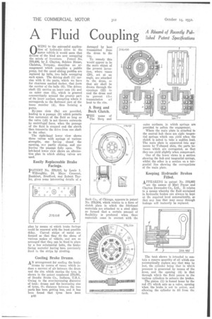
WING to the suCcessful application of hydraulic drive to the motor vehicle it would seem that devices of the kind are now occupying
the minds of inventors. Patent No. 379,496, by J. Clayton, SoLsbro House, Chelston, Torquay, describes an arrangement which resembles a paddle pump, but the usual sliding paddles are replaced by balls, two balls occupying each space. The driving shaft (1) carries with it the parts, which we have for clearness marked darker, that form the carrier of the balls (6). The driven shaft (2) carries an inner cam (4) and an outer case (8), which is grooved concentrically around the greater part of its inner surface, excepting where it corresponds to the flattened part of the inner member (4), thus forming a pump. By-pass slots (9a) are provided, leading to a passage (9) which permits free movement of the fluid so long as the valve (10) is not thrown outwards by centrifugal force, when the passage of the fluid is stopped and the clutch then transmits the drive from one shaft to the other. The right-hand lower view shows three valves with springs of various strengths, one having closed the opening, one partly closing, and one leaving the passage fully open. The left-hand lower view shows an alternative plan in which sliding valves are used.
Easily Replaceable Brake Facings.
PATENT No. 379,618, by Louie I. Willoughby, 24, Mayo Crescent, Bankfoot, Bradford, and Robert Taylor, gives some interesting details of a plan by means of which brake facings could be renewed with the least possible delay. Curved strips of metal are formed so that they fit the shoes of various makes of vehicle, and are so arranged that they can be fixed in place by a few substantial bolts, the brakefacing material having been previously fixed to the strips by riveting.
Cooling Brake Drums.
AN arrangement for cooling the brake drums by means of vanes which induce a current of air between the drum and the rim which carries the tyre, is shown in the patent numbered 379,091, of Bendix Brake Co., Indiana, U.S.A. Owing to the ever-increasing diameter of brak ) drums and the increasing size of tyres, tls.; distance between the two parts has been getting less, and it has been found that tyres have been
MO damaged by heat transmitted from the drum to the rim.
To remedy this would appear to be the main object of the present invention, where vanes (20), set at an angle, are attached to the drum, so that air shall he drawn through the openings (22) to cool the drum and to prevent the
transmission o f heat to the rim.
A Borg and Beck Clutch.
THE name of The Borg and Beek Co., of Chicago, appears in patent No 379,504, which relates to a form of clutch plate in which the frictional materials are attached to a steel plate so formed that a certain amount of flexibility is produced when these materials come in contact with the outer surfaces. in which springs are provided to soften the engagement.
Where the main plate is attached to the central hub there are eight tangential springs which can yield when the clutch is asked to take a sudden load. The main plate is separated into segments by T-shaped slots, the parts between which are corrugated, so that they can yield slightly when compressed.
One of the lower views is a section showing the hub and tangential springs, whilst the other is a section on a tangential line showing the corrugations of the main plate.
Keeping Hydraulic Brakes Filled.
APPEARING in patent No. 378,992
are the names of Matt Payne and Clayton Dewandre Co., Ltd., It relates to .a means whereby the fluid contained in hydraulic brakes can always be kept at the required level automatically, so that any loss that may occur through leakage will instantly be replaced.
The tank shown is intended to contain a reserve quantity of oil which can automatically replace any that may be lost, the cylinder being that in which pressure is generated by means of the lever, and the opening (4) is that through which the fluid passes to the various cylinders to actuate the brakes. The piston (1) is forced home by the rod (7) which acts as a valve, opening when the brake is not in action, and allowing the cylinder to fill from the tank.