


Testing Brakes in the Laboratory
Page 43
If you've noticed an error in this article please click here to report it so we can fix it.
How Wear, Performance and Fade Characteristics of Brake Assemblies are • Evaluated by Short-period Tests at the Girling Works
AMACH1NE now being used by Girling, Ltd., King's Road, Tyseley, Birmingham, to analyse the wear, performance and fade characteristics of all types of vehicle brake, incorporates what the concern considers to be the best features of all contemporary apparatus. The inertia braketesting plant, which was later built by Heenan and Froude, Ltd., Worcester, is installed at the Tyseley works in Birmingham in a sound-proof room, which is equipped with forced-draught fans for the controlled cooling of the drums and other ancillary equipment, appropriate to a self-contained laboratory.
Faults Corrected Although the tests conducted are often concerned with the properties of facings and drums supplied by other component manufacturers, the design of the actuating mechanism must be correlated to the function of these parts and any faults corrected before production is started. Whilst the laboratory work does not obviate the need for road testing, it reduces the overall time required for any research programme, and often enables results to be achieved which would be impossible if analysis were based on road tests in this country.
The machine follows normal practice in that the brake-dnurt shafts are driven by freely rotating flywheels, which are initially accelerated to a predetermined speed by an electric motor. Many features are, however, of original and outstanding interest, particularly with regard to the independent operation of duplicated test-gear assemblies, the method of mounting the flywheels, the design of the torsion box and details of the automatic time-cycle mechanism.
Two tests may be conducted at the same time, or a brake-gear assembly may be in process of being fitted at one end while a test is in progress at the other. A set of large and small flywheels on each side is divided into a number of discs, which can be transferred from a non-operating to a driven position without demounting.
Inertia Effects The use of a " pure-torsion " shaft in the torsion box Ortually obviates inertia effects when readings are taken, and, if necessary a record of torque measurements may be made on a Cambridge vibrograph. The time-cycle apparatus is of the graduated-drum type and complete resetting for a new test is possible in less than 20 minutes.
For testing commercial-vehicle brake assemblies, the flywheel shafts are accelerated to a maximum of 400 r.p.m. For private car components the maximum speed is 1,000 r.p.m,, and when testing the brake gear of racing cars, aircraft and tanks, the flywheel can be taken up to a speed of 2,500 r.p.m.
The maximum torque available in any of the ranges is 40,000 ft.-lb. and the kinetic energy of the revolving mass on each side is 61m. lb,-ft. at maximum r.p.m.
Power for accelerating the flywheels is provided by a B.T.H. variable-speed 100 h.p. D.C. motor, electronically controlled by a B.T.H. Ernotrol unit, which converts the 440-volt alternating current to direct current. The speed required is preselected by a control on the instrument panel, and when this speed is reached, the flywheel clutches are automatically disengaged and the motor switched off, leaving the flywheels to rotate without restraint until the brake is applied.
The power from the motor is transmitted by a David-Brown manually operated three-speed gearbox to an airoperated clutch and thence to a spiralbevel transfer box, which forms the T drive. On each side of the transfer box the drive is taken through an airoperated clutch to the flywheels, the brake-assembly mounting flange and via the brake, to the torsion box.
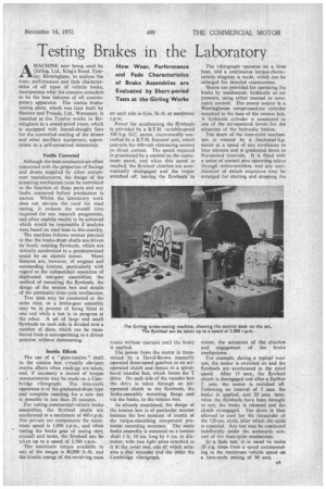
As already mentioned, the design of the torsion box is of particular interest because the low moment of inertia of the torque-absorbing component promotes recording accuracy. The static brake assembly is mounted on a torsion shaft 1 ft. 10 ins, long by 4 ins, in diameter, with two light arms attached to it at the inner end, one of which actuates a dial recorder and the other the Cambridge vibrograph.
The vibrograph operates on a time base, and a continuous torque-characteristic diagram is made, which can be enlarged for detailed examination.
Means are provided for operating the brake by mechanical, hydraulic or air pressure, using either manual or automatic control. The power source is a Westinghouse compressed-air cylinder mounted in the base of the torsion box. A hydraulic cylinder ts connected to one of the air-operated levers for the actuation of the hydraulic brakes, The drum of the time-cycle mechanism is rotated by a fractional-h.p. motor at a speed of one revolution in four minutes and is graduated down to five-second intervals. It is fitted with a series of contact pins operating relays through micro-switches, and any combination of switch sequences may be arranged for starting and stopping the motor, the actuation of the clutches and engagement of the brake mechanisms.
For example, during a typical wear test, the motor is switched on and the flywheels are accelerated to the rated speed. After 15 sees., the flywheel clutch is disengaged and after a further 2 secs. the motor is switched off. Following an interval of 5 secs. the brake is applied, and 20 secs, later, when the flywheels have been brought to rest, the brake is released and the clutch re-engaged. The drum is then allowed to cool for the remainder of the 120-sec. cycle, after which the cycle is repeated. Any test may be continued indefinitely under the automatic control of the time-cycle mechanism.
In a fade test, it is usual to make .10 4-g. stops from a speed corresponding to the maximum vehicle speed on a time-cycle setting of 90 secs.