


COMMERCIAL MOTOR BODIES.
Page 32
If you've noticed an error in this article please click here to report it so we can fix it.
A Resume of Recently Published Patents.
ALTHOUGH invention with regard to chassis construction is a long way from being dormant, there is always the feeling that, having got a fairly satisfactory machine, one • may turn with a measure of relief to the coachbuilders' portion of the vehicle and endeavour to discover what improvements, if any, may
be effected there. Naturally, there is likely to be more scope in this section of the motor vehicle manufacturer's art, particularly amongst commercial vehicles, since it is probable that, if his wants were completely satisfied, it. would be found that each and every type of trader could do with his distinctive type ofithody, differing from all others in some one or two respects, and particularly with regard to the interior fittings. Not so with the chassis, for, with one or two notable exceptions, it is a fact, that the same chassis is suitable for every different trade.
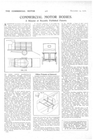
One attempt to meet special require ments of this nature is embodied in Specification No. 186.215, entitled " Im• provements in Bodies for •Motot Vehicles," which has been published during the last week or so by the Patent Office, on behalf of E. Saxon. It de scribes a type of body especially designed to meet the requirements of farmers, cattle, sheep, and pig solemner, and others who have to transport animals, agricultural produce and general suerchandize. It is, therefore, likely to be of special interest to the country carrier; • particularly those who work in districts syhere regular weekly markets are held.
'the body• devised by the inventor is shown in one of the accompanying illustrations. It is Stepped, or projects down • immediately behind the rear axle of the chassis, and has short, fixed, vertical sides, as well as extensiens for those sides, tho said extensions being quickly detachable.
Outwardly projecting brackets are provided at the ton of e.ach side, as shown in the end view of the, body. These brackets are designed to facilitate the use of a second platform. above the main one, so as to increase the bulk rapacity of the vehicle.
A movable gateway is provided for that portion of the body in advance of the stepped portion, to separate it, when desired, into two compartments. The tailboard is hinged at the bottom, and may be lowered so that its top edge rests upon the •ground, when the board becomes a convenient ramp up which animals may walk, or be led, into the body.
Other Patents of Interest.
• Another direction in which commercial motor bodywork, or accessories thereto, has been receiving considerable attention for some time now is in connection with tipping gear. In that regard the name of M. F. Edwards is a fairly familiar one. In specification No. 186,145 this inventor describes an improved form of hydraulic tipping mechanism, designed to work in conjunction with his well-known threeway tipping gear. The principal feature about, this invention is the arrangement and mounting of the ram cylinders, which are supported on etrunnions designed to allow of.swivelling in two directions. A long bar, mounted in trunnions on the sides of the frame. Carries both cylinders, which are on other trunnions on the bar. • The prevention of accidents in connection with motor coaches is another source of invention, W. J, Dickinson describes, in No. 186,224, a form of skid which . should be very useful in that regard. A plain slipper, or shoe, is attached to a curved bar, which is connected to some form of release gear, operated by the driver, so that when he thinks needful the shoe is dropped, and automatically slips under the rear wheel, braking it. Other methods of operating the gear are referred to, such as by a governor which, when the vehicle speed exceeds a certain predetermined limit, releases these skids, and also disengages the clutch.
C. 0. Nevatt, in No. 186,247, describes a method of mounting a semi-elliptic spring so that its effective length automatically varies with the load, becoming shorter and stiffer as the load increases. One end of the spring is connected to the frame by shackles, which are anchored to the frame at a point below the spring, so placed that the arc through which the links move takes up the amount which the spring lengthens when flattening under load, so keeping the centre of the spring in the same perpendicular line throughout its movement. At the same time the ends of the spring bear against cam-shaped blocks designed so that, as the spring flattens, the points of contact between springs and blocks come nearer together, shortening the effective length of the spring.
The detachable seat which is the subject. of patent. specification No. 186,312, taken out by G. F. Podmore, is clearly intended for use in connection with the rapid conversion of a goods-carrying vehicle from its usual purpose, to that of passenger conveyance. The accompany ing illustration is self-explanatory. • A most pretentious type of vehicle, designed to carry a couple of Tanks; or large field guns, is described in No. 186.261, by E. Rimailho. It consists essentially of a trussed platform, pivoted to, and resting upon, two three-wheeled bogies, one at each end. The bogies are electrically driven, the necessary current being provided by generating sets mounted upon the load-carrying part of the vehicle.
The safety drawbar counting which is the subject of No. 186,248. by W. E. Tucker. has an ordinary hook for attachment to the tractor, and a looped spring bar, the ends of which just meet, for coupling to the trailer or implement. A ring round the spring loop, with setscrew adjustment, regulates the tension and the grip which this spring loop places upon the implement. Excessive load opens the ends of the loop and releases the trailer. • Specification No. 186,172 refers to H. Ferguson's well-known tractor plough, and describes means whereby the depth of cut 'made by the plough may be regulated. The said means may be a wheel, adjustably secured to the imple. ment frame,•and arranged to bear upon the ground during ploughing.