


An Unusual Injection System
Page 52
If you've noticed an error in this article please click here to report it so we can fix it.
A Résumé of Patent Specifications that 'have Recently been Published
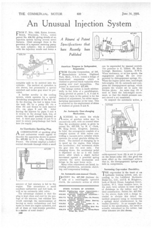
rROM F. Ritz, 1263, Eaton Avenue,
Beloit, Wisconsin, U.S.A., comes patent No. 926,791 giving details of an injection system having several novel features. Chief amongst these is the provision Of a separate metering pump for each cylinder ; this is combined with the injection nozzle and forms a complete unit to be screwed into the cjdinder. The method of operation is not shown, but presumably a special camshaft and rocker gear must be provided.
A further novelty is the cooling system, which operates by a special circulating arrangement of the fuel oil. In the drawing, the fuel is taken from the tank (5) by a pump (6) via a filter (8) and thence to each injector (1), via pipes 9 and 10. After leaving the injector by pipes 3 and 4 it returns to the storage tank, less, of course, the small quantity injected as fuel. A third pipe system (2 and 7) is used to return pump-leakage fuel back into the supply.
An Unorthodox Sparking Plug.
A COMBINATION of sparking plug 1-3, and carburetter would appear to describe the apparatus shown in patent No. 427,061 by P. L. Alby, Bordeaux, France. The scheme employs a hollow central electrode through which a small
amount of fuel mixture is fed to the engine. This necessitates a small auxiliary carburetter and fuel tank, as well as an automatic inlet valve.
The advantage claimed is that the plug is kept clean and cool by the passage of the mixture, but whether this would. outweigh the inconvenience of having as many carburetters and fuel tanks as there are engine cylinders, and all of them at high-tension potential, is a matter of some doubt!
B42 American Progress in Independent Suspension.
E'ROM Chrysler Corporation, of 341,
Massachusetts Avenue, Highland Park, Mich., U.S.A., comes a design of front-wheel suspension which is claimed to prevent track variation when passing over road inequalities. The patent is numbered 427,460.
. The linkage .system is made substantially in the form of a parallelogram, being pivoted at points 1, 2, 5 and 6. The chief claim in the patent is for the method of adjustment, for either manufacturing inaccuracies or for wear. This is achieved by the employment of shims or washers at points 2 and 6.
An Automatic Gear-changing Mechanism.
ASCHEME by which the whole series of gearbox ratios may he successively used, with no control other than the accelerator pedal, is given in patent No. 427,735, by R. C. Clerk, 60, King Street, Kingston, Jamaica. In brief, the arrangement consists of a complex system of slide valves controlling a vacuum-servo cylinder which operates the actual gearbox sliding elements. The method of changing up is to speed up the engine, then release the accelerator ; this movement shifts the gear into the next ratio. For changing down, the accelerator pedal is depressed as far as it will easily move, after which a slight further movement against a powerful spring operates the servo mechanism and brings in the next lower ratio.
Many other refinements are listed, including preselection, automatic clutching, and compression braking.
An Automatic-cum-manual Clutch.
DATENT No, 427,649 discloses de]. tails of a centrifugally operated clutch, the automatic action of which
can be superseded by manual control. The patentee is E. Gillett, 32, Marlborough Mansions, London, N.W.6. When stationary, or at low speeds, the engagement springs (6) are overpowered by disengagement springs (1). When the engine speed rises, centrifugal bob-weights (2) fly outwards and compress the disengagement springs, which permits the weaker set to unite the friction plates. An outer ring (3) is used to limit the bob-weightmovement, so that the clutch pressure cannot exceed a set maximum.
To suspend the automatic action„ a
cable-operated lever (5) is set to press on the thrust collar (4) ; this gives the same effect as the centrifugal action ; that is, the disengagement springs" are held in compression.
Increasing Cup-washer Durability. TE cup-washer is the heart of an
HE braking system, and, according to the Lockheed Hydraulic Brake Co., Ltd., and E. B. Boughton, both of Brock House, Langham Street, London, W.1, these washers have, in the past, been subject to some degree of shrinkage in the rubber used for their construction. Patent No. 427,(1.88, by the above, deals with a design intended to obviate this defect, the method proposed being to incorporate a springy metal reinforcement in the washer assembly. In an example illustrated in the specification, the metal is actually vulcanized in the rubber, but other schemes are also shown.