


Non-detonating High-compression Head
Page 52
If you've noticed an error in this article please click here to report it so we can fix it.
A Resume of Recently Published Patent Specifications Obtainable from the Patent Office, Price Is. each.
PATENT No. 506,400 discloses a design of combustion head making for increased efficiency, with which goes economical running. The patentees are A. Taub, and Vauxhall Motors, Ltd„ Luton.
Economy can be improved by high compression only if detonation be prevented, and the invention is directed towards this goal. According to the patent, the most favourable form of chamber is one in which, as the flame spreads from the plug, the maximum cross-sectional area is reached at 30 per cent, of the flame travel. The anti-detonating feature consists of a narrow tail-end (1) on the side remote from the plug. This space, by virtue of its large area/volume ratio, and its corrugated cooling surfaces, prevents the self-ignition of the last part of the charge. • A Constant-pressure Combustion System.
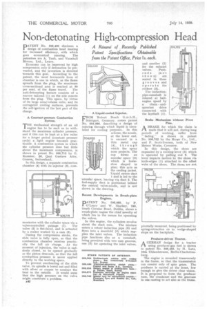
-r-HE mechanical strength of an oil • 1 engine has to be such as to withstand the maximum cylinder pressure, and if this can be kept at a low value for a longer period (constant pressure cycle) a light engine becomes practicable. A combustion system in which the cylinder pressure rises but little above the maximum compression, is shown in patent No. 505,713 by G. Kammer, 50, Quai Gustave Ador, Geneva, Switzerland.
In this design, a separate combustion chamber (4) with its injector (9), com municates with the cylinder space via a valve-controlled passage (1). The valve (2) is flat-faced, and is actuated by a rocker worked by a cam (5).
During the compression stroke, the slide valve is fully open, so that the combustion chamber receives practically the full air charge. At the moment of injection, the valve is suddenly closed, to be opened gradually as the piston descends, so that the full combustion pressure is never applied directly to the working space.
To prevent overheating of the slide valve, its spindle is bored out and filled with silver or copper to conduct the heat to the outside. . It would seem that the high pressure on the valve might constitute a problem.
s42 A Liquid-cooled Injector.
FROM Robert Bosch G.m.b.H., Stuttgart, Germany, comes patent No. 504,988, describing a design of inject oa through which liquid is circulated for cooling purposes. In this scheme, the nozzle, at the lower end, is encased in a thin metal cap (4), through which the spray nose projects. The cap forms an annular space (3) which is horseshoe shaped in plan; this acts as the cooling jacket. Liquid enters duct 1 and is led to the -annular space, leaving via duct 2. The fuel-supply duct is positioned behind the central valve-needle, and is not shown in the drawing.
Recent Developments in Swath-plate Engines.
DATENT No. 506,098, by P. 1 O'Leary and W. Sharkey, 246, South Circular Road, Dublin, shows a swash-plate engine the chief novelty of which lies in the means for operating the valves.
In this engine, the cylinders revolve about the shaft axis. The mixture enters a rotary induction pipe (6) and flows into a manifold (4) which supplies the inlet valves. The induction pipe functions also as a camshaft, being provided with two cam grooves, one (5) for operating the inlet valves, and another (2) for the exhaust valves. Push rods (not
shown) are seated in these grooves. and operate the rockers (3).
The inductionpipe-camshaft is rotated at halfengine speed by
a chain andsprocket drive connected with the Iayshaft (1)
Brake Mechanism without Pivot Pins.
A BRAKE for which the claim is PA made that it will not, during long period's of working, suffer from " fading," is shown in patent No. 506,752 by the RoNier Co., Ltd., and P. Scott-Iversen, both of New Meteor Works, Coventry.
In this design, the shoes are expanded by a rocking lever (3) which is operated by pulling rod 2. The lever imparts motion to the shoes via knife-edges (1) attached to the offset webs of the shoes. The shoes are not
pivotally mounted, being positioned b; spring-retraction on to wedge-shaped stops on the backplate.
Producer-driven Tractor.
AGERMAN design for a tractor using producer-gas fuel is shown in patent No. 506,462, by H. Lutz, 194a 1.1hlandstrasse, Berlin-Charlottenburg.
The engine is mounted transversely in the frame, so that the transmission can consist only of spur gears. The producer is carried at the front, low enough to give the driver clear vision. It is proposed to form the producer base, the crankcase and the gearcase in one casting to act also as the frame.