


A Combined Hydraulic Clutch and Epicyclic Gear
Page 62
If you've noticed an error in this article please click here to report it so we can fix it.
A Resume of Recently Pubuslzed Patent Specifications INpatent No. 393,294, J. G. Swan, 14, Old Square, Lincoln's Inn, London, describes a combination of a hydraulic clutch of the Fottinger type with various conical clutches and an epicyclic gear, by means of which he is able to produce several changes of speed ratio without the engagement of sliding gears or dog clutches.
The specification is a long one, showing no fewer than seven different applications of the arrangement, and containing 31 claims. It will therefore be seen that in the available space it is impossible to give many details, but it will be apparent that by the manipulation of the cone clutches (16 and 26) and by the main hydraulic elutch, the free wheel (21), which prevents backward movement, and the epicyclic gear, a great variety of speeds may be obtained with smooth engagement and without shock.
Barring Air from Hydraulic Brake Systems.
IN their patent No. 392,933, the Bendix Brake Company, Indiana, "U.S.A., points out that the presence of any substantial amount of air in the lines of hydraulic brakes renders them almost inoperative owing to
its compressibility. The invention, it is claimed, prevents entry of air into such systems.
The sectional view shows the master cylinder, which has two pistons, (110 and 122), the latter being operated by the push rod from the pedal lever. The two pistons are separated by a space, but are able to act together by means of the extension from 110, which is the actual piston, to deliver fluid to all the brakes vie opening 42.
A pipe (52) leads from a reservoir to the left, expelling the fluid to the pistons, and by the ducts shown and a valve (140) to the actual pressure chamber in front of the piston (110). The action when the brake is applied is as follows :—the piston (122) is pressed the to the left until it meets the extension from the other piston, which it moves to the left, expelling the fluid to the brakes. As this takes place the conical end of the piston allows the valve to close, thus cutting off communication with the reservoir, and acting in the usual manner. Should a sudden release of the brake be made, which in ordinary circumstances might induce air to enter the system, piston 122 can move to the right, and any vacuum caused will only draw fluid from the reservoir, some of which can find its way to the chamber in front of piston 110, thus replenishing the whole system with fresh fluid.
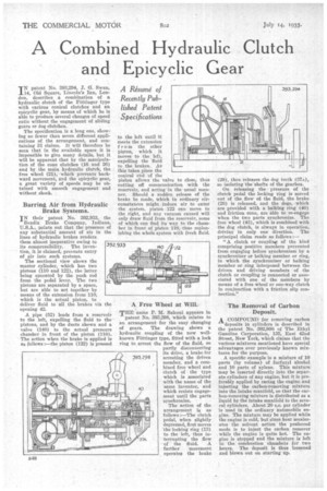
A Free Wheel at Will.
THE name P. M. Salerni appears in patent No. 393,298, which relates to an arrangement for the easy changing of gears. The drawing shows a hydraulic coupling of the now wellknown Fottinger type, fitted with a lock ring to arrest the flow of the fluid, so partly disconnecting its drive, a brake for
393,298 arresting the driven member, and a combined free wheel and clutch of the type which is associated with the name of the same inventor, and which resists engagement until the parts synchronize.
The action of the arrangement is as follows :—The clutch pedal, when slightly depressed, first moves the locking ring (13) to the left, thus in
37A tempting the flow of the fluid. A farther, movement operates the brake
(29), then releases the dog teeth (37A), so isolating the shafts of the gearbox.
On releasing the pressure of the clutch pedal the locking ring is moved out of the flow of the fluid, the brake (29) is released, and the dogs, which are provided with a balking ring (40) and friction cone, are able to re-engage when the two parts synchronize. The free wheel (43), which is combined with the dog clutch, is always in operation, driving in only one direction. The principal claim reads as follows:—
"A clutch or coupling of the kind comprising positive members prevented from engaging before synchronism by a synchronizer or balking member or ring, in which the synchronizer or balking member or ring interposed between the driven and driving members of the clutch or coupling is connected or associated with one of the members by means of a free wheel or one-way clutch in conjunction with a friction slip connection."
The Removal of Carbon Deposit.
A COMPOUND for removing carbon
deposits in cylinders is described in the patent No. 392,998 of The Ethyl Gasoline Corporation, 135, East 42nd Street, New York, which claims that the various mixtures mentioned have special advantages over previously known mixtures for the purpose.
A specific example is a mixture of 10 parts (by volume) of furfuryl alcohol and 10 parts of xylene. This mixture may be inserted directly into the separate cylinders of any engine, but it is preferably applied by racing the engine and injecting the carbon-removing mixture into the intake manifold, so that the carbon-removing mixture is distributed as a liquid by the intake manifold to the several cylinders. About 20 c.c. per cylinder is used in the ordinary automobile engine. The mixture may be applied while the engine is cold, but since heat accelerates the solvent action the preferred mode is to inject the carbon remover while the engine is quite hot. The engine is stopped and the mixture is left in the combustion chambers for two hours. The deposit is thus loosened and blown out on starting up.