


A MAXIMUM-LEGAL-1_40AI FOUR-WHEELER TESTED
Page 56
Page 57
Page 58
If you've noticed an error in this article please click here to report it so we can fix it.
The Halley Four-cylinder a-tonner Proves _itself an Economical Machine. Moderate Power-to-weight Ratio, Low Loading Line and Large Platform Area Among its Numerous In teresting Features
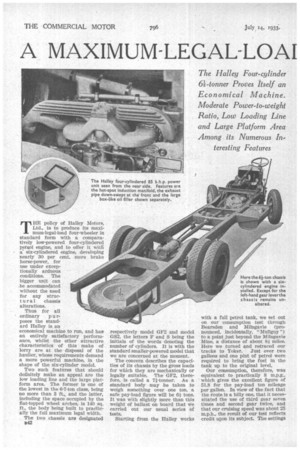
THE policy of Halley Motors, Ltd., is to produce its maximum-legal-load four-wheeler in standard form with a comparatively low-powered four-cylindered pettpl engine, and to offer it with a six-cylindered engine, developing nearly 30 per cent, more brake horse-power, for use under exceptionally arduous conditions. The bigger unit can be accommodated without the need for any structural chassis alterations.
Thus for all
ordinary p u rposes the standard Halley is an economical machine to run, and has an entirely satisfactory performance, whilst the other attractive characteristics of this make of lorry are at the disposal of the haulier, whose requirements demand a more powerful machine, in the shape of the six-cylinder model.
Two such features that should definitely make an appeal are the low loading line and the large platform area. The former is one of the lowest in the 6-7-ton class, being no more than 3 ft., and the latter, including the space occupied by the flat-topped wheel arches, is 140 sq. ft., the body being built to practically the full maximum legal width.
The two chassis are designated B42 respectively model GF2 and model 6S2, the letters F and S being the initials of the words denoting the number of cylinders. It is with the standard smaller-powered model that we are concerned at the moment.
The concern describes the capacities of its chassis by the gross loads for which they are mechanically or legally suitable. The GF2, therefore, is called a 71-tonner. As a standard body may be taken to weigh something over one ton, a safe pay-load figure will be 61 tons. It was with slightly more than this weight of ballast on board that we carried out our usual series of tests.
Starting from the Halley works
with a full petrol tank, we set out on our consumption test through Bearsden and Milngavie (pronounced, incidentally, "Mullguy ") to a point just beyond the Milngavie Mine, a distance of about 81 miles. Here we turned and retraced our tracks to Yoker. Just over two gallons and one pint of petrol were required to bring the fuel in the tank up to the original level.
Our consumption, therefore, was equivalent to practically 8 m.p.g., which gives the excellent figure of 51.8 for the pay-load ton mileage per gallon. In view of the fact that the route is a hilly one, that it necessitated the use of third gear seven times and second gear twice, and that our cruising speed was about 25 m.p.h., the result of our test reflects credit upon its subject. The settings
of the Solex carburetter used were, main jet, 160; compensating jet, 70; and choke, 34.
In Clydebank, a suburb of Glasgow, there is an acclivity called Kilbowie Hill, with a maximum gradient of 1 in 9, and about a quarter of a mile in length. The steepest portions, at the commencement and nearing the summit, were ascended in second gear, whilst the easier part midway up the hill wag negotiated in third. Our speed never fell below 10 m.p.h., and the climb raised the temperature of the cooling water from 160 degrees F. to 190 degrees F.—about 130 degrees F. above atmosphere.
The lorry, in the form we tested, with a 32.4 h.p. engine .and standard 8.66-to-1 axle ratio should be capable of climbing hills up to 1 in 7 or even 1 in 6 with power in hand, but for grades of exceptional severity the lower ratio or the larger engine would probably be required.
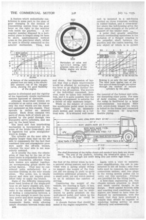
Reference to an accompanying graph shows the remarkably constant acceleration on the level from speeds even so low as 10 m.p.h., the curve being nearly straight from this figure to well over 30 m.p.h.
Another point that should be recorded is the quick and easy gear changes that are possible. The ability to change from a lower to a higher gear without material loss of time and speed is a factor fairly important in economical running, as it enables the upper stretches of the type of hill which begins steeply and eases off as height is gained to be ascended in a higher ratio than would otherwise be possible.
Torque, incidentally, does not fall off lower down the scale of r.p.m. so markedly as many other petrol engines that we have tested, for it was actually possible in top gear to move off from rest on the level without slipping the clutch excessively and without the engine knocking or exhibiting undue signs of distress. A feature which undoubtedly contributes in some part to the ease of gear changing is the method of transmitting motion from the gear lever on the right to the selector
rods inside the gearbox. A triangular member disposed in a horizontal plane is hinged along its base to short, approximately vertical arms on the gear-lever shaft, whilst its apex is directly connected to the selector mechanism. Thus, lost
A feature of the acceleration graph, plotted from our tests, is the remarkably constant rise of the top-gear curve, showing the good flexibility of the engine.
motion is eliminated and the rigidity of the ingeniously simple mechanism ensures lightness of operation.
Although front-wheel brakes are available at an extra cost, brakes on only the rear wheels are the standard equipment on this chassis. They operate in rather an unusual manner. Each drum contains two pairs of shoes, both of which are expanded by the pedal through two Dewandre servo cylinders, and one pair by the hand lever, The hand and foot interlocking mechanism is incorporated in the arms of the brake cross-shaft, and is ingenious but quite straightforward in design.
The cylinder on the near side is slightly larger than that on the off side to compensate for the fact that combined foot and atmospheric pressure apply the off-side brakes, whereas the near side is not mus cularly assisted.
As is usually the case, the elimination of time lag by the use of the hand brake is responsible for the improved retardation afforded when both brakes are applied together. An accompanying graph shows the actual figures. They may be considered quite satisfactory for a machine braking on the rear wheels alone. The pedal, too, is ideally placed and does not require great effort fully to apply the brakes.
Signs of the difficulty inseparable from hand brakes of the single-pull type on all heavy chassis are, however, to be found on the Halley. We refer to the almost impossible task of finding a compromisebetween a lever long enough to exert the necessary power and short enough to keep the travel of its handle within reasonable limits, while allowing ample clearance between brake shoe
13114
and drum. Our impression of layout was that a slight improvement would be effected by arranging for the lever to go slightly farther forward in the off position. The stature of the individual concerned, however, must be taken into consideration, and it is quite possible that the existing arrangement is suitable for a driver of only moderate height.
While on the subject of controls, the accelerator pedal must be mentioned. This has an unusually short motion and works on a vertical axis. It Is situated well under the foot of the driver when he is in a natural sitting posture, and is provided with a spring amply strong to support the weight of the foot, yet not too strong to yield to quite moderate additional pressure. It is a small point, yet one which seemed to us to enhance the comfort of driving.
Considering the weight of the vehicle, the steering is light ; it has, too, a pronounced self-centring action. The clutch can be withdrawn by gentle pressure on the well-placed pedal, and takes up the drive as smoothly as could be wished.
A chassis feature that should be noted is the engine suspension. The unit is mounted in a sub-frame carried on three trunnions working in rubber bushes, and a cross-mesaher above the bell-housing gives the frame extra strength at the point of support of the hinder ones. ..;„,
A point that greatly simplifies certain overhauling operations is the inclusion of a flanged coupling in the propeller shaft between the gearbox and the centre bearing, the sole object of which is to permit
Braking is on only the rear wheels. The hand lever applies two of the four pairs of shoes brought into action through the medium of vacuum cylinders by the pedal.
the removal of the former unit without disturbing other parts. For ease of daily routine, replenishment of th.3 sump is facilitated by a large cast-aluminium box-shaped filler with screw-down hinged lid, which is bolted to the frame and connected to the crankcase by large-bore flexible piping.
Again with a view to maintenance simplification, the cab is constructed to lift off bodily ; only four bolts need be removed, the Autovac connections undone, and two plugs in the wiring system pulled out to carry out this operation. Fittings are provided for the lifting books.
A first-class engineering job, this chassis reveals attention to detail and much careful thought in its design. Built amidst Scottish hills and exacting road conditions, its designers are bound to have been influenced by environment, with the result that they have produced a vehicle that should be capable of rendering lasting service at once efficiently and economically.