


Patents Completed.
Page 20
If you've noticed an error in this article please click here to report it so we can fix it.
Complete specifications of the following patents will be sent to any address in the United Kingdom upon receipt of eightpence per copy at the Sales Branch, Patent Office, Holborn, W.C.
FORCE FEED LUBRICATORS.Wakefield—No. 29,366, dated 15th Deember, 1909.—This invention relates to farce-feed lubricators, and it has for its 9 object to obviate the disadvantage of the sight tubes becoming filled with oil. A pump is placed in the oil reservoir, and is actuated by means oi an eccentric in a shaft driven from any convenient working part of the machinery. The pump draws oil past a ball valve from a small cup situated at the bottom of the sight tube and forces it past a non-return valve to the parts of the machinery to be lubricated. The cup in the sight tube is at once replenished with oil from the inlet at the top of the sight tube, owing to the partial vacuum which is established. The amount of oil drawn from the cup is determined by a needle valve arranged below the ball valve. To start the lubricator, the cup is first. filled by removing a screw cap at the top of the sight tube. The reservoir is next filled to the level of the top of the sight tube, so that the top chamber of the sight tube is filled with oil. It, will be seen that, with this arrangement, the air contained in the sight glass has no means of escape, and, consequently, the sight glass cannot become flooded with oil.
PISTON RINGS.--Lanehester, Peache and Winans and Robinson, Ltd.—No. 2,958, dated 8th February, 1909—Ac• cording to this invention, piston rings are made to the correct out-sprung form of the ring, the gap in the ring being subsequently made by removing a suitable portion of metal. This is effected by mounting on the spindle of the lathe a finished ring having the gap filled by a suitable piece of metal. Bearing against. thisfinished ring, is a roller carried by an arm that is keyed on to a shaft, which in turn carries and controls the movements of a cutter to and from the work. In this way, the cylinder, which is to he
made into packing rings, is first reduced to the correct out-sprung form of the ring and is subsequently divided, and the piece of metal is removed to form the gap. TIRES.—Whiteway and Another.---No. 24,338, dated 23rd October, 1909.— This invention consists in placing an inextensible tube between the outer cover and the air tube of a pneumatic tire.
The said tube is split circumferentially, so that the edges overlap to form a lapjoint at its split portion. The tube is preferably made of canvas cut on the bias and a thin layer of rubber is formed on its inner surface. The edges are formed of rubber and the overlapping portion is coated externally to prevent chafing. The tube is built up on a suitably-shaped mandrel, and, when completed, it is vulcanized thereon to give it the shape it will assume when in position in the tire.
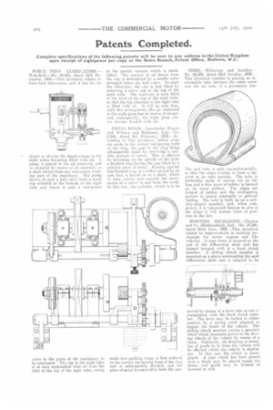
HOISTING MECHANISM.—Clayton and Co. (Huddersfield), Ltd.—No. 14,596, dated 22nd June, 1909.—This invention relates to improvements in hoisting mechanism for motor wagons and like vehicles. A rope drum is secured on the end of the differential shaft and has formed integral with it, a fixed clutch member. A sliding clutch member is mounted on a sleeve surrounding the said differential shaft and is adapted to be
moved by means of a lever into or out of engagement with the fixed clutch member. The lever may be locked in either position by a spring catch adapted toengage the frame of the vehicle. The sliding clutch member carries a sprocket wheel which transmits power to the driving wheels of the vehicle by means of a chain. Ordinarily, the hoisting or lowering of goods to or from the vehicle will be effected whilst the vehicle is stationary. In this case the clutch is disengaged. A rope which has been passed over a block may be placed -round the drum, and goods may be hoisted or lowered at will.