


A New Five-speed Gearbox D ESIGNED mainly for the heavier types
Page 56
If you've noticed an error in this article please click here to report it so we can fix it.
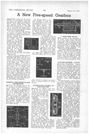
of road vehicle, a new gearbox forms the subject of patent. No. 607,791, which comes from J. Naylor, and Atkinson Lorries (1933), Ltd., Mai sh Lane, Preston, Lancs. The chief aim is to provide five speeds and a reverse, whilst at the same time keeping the box to a minimum length.
As will be seen from the drawing, the gearbox, in general, follows conventional lines, having an input shaft (I) driving a layshaft via a fixed gear-pair (2), whilst the output shaft is centred in the driving spindle and is splined for its whole length. On the layshaft is a free gear (3), a fixed pinion (4) and a second fixed but wider pinion (5). On the Output shaft is a sliding splined gear (6), a double one (7) free on the shaft, and another sliding one (8). The five ratios Are obtained with the following combinations: Top gear is a straight-through drive from the input shaft to a ,dog on gear 6; fourth speed
• couples gear 4 to 3, thence via gear 6 to the output shaft. Third speed is obtained by sliding 7 to the left to couple it to 6, the drive arriving from the layshaft via 4. Second speed utilizes the pair 5-7, but the latter is then slid to the right to engage a spline(' collar on the output shaft. First or lowest speed is obtained by meshing gear 8 with a small pinion.:(9) on the layshaft. Reverse uses gear 8 also, by engagement with the usual idler (10). The patent also Covers some' details of the gear-shifting arrangements.
STEERING ARRANGEMENTS FOR SIX-WHEELERS
PATENT No?-607,898 refers to the steering of sit-wheelers having two steered wheels and a four-wheeled bogie. With such an arrangement,the rear set of wheels normally takes no part in the steering, and this is considered to be a defect, leading to excessive tyre-wear and a tendency to skid. The patentees, P. Williams, and H. Houghton, 99, Cromwell Avenue, Whalley Range, Manchester, describe a four wheeled assembly in which corrections are made in response to front-wheel steering The drawing shows a twoaided assembly in which the two axle-casings (1 and 2) are ball-jointed (as at 3) to a common central member. The• outer ends of each two axlecasings are connected by a lazytongs mechanism (4) into which is built an hydraulic cylinder (5). These are piped to a fluid system controlled by the steering gear of the front wheels.
In operation, when the front wheels are steered, a small quantity of liquid is admitted to one of the hydraulic cylinders and withdrawn from the other, and the net result is to pull the axles together on one side of The vehicle, and to separate them on the odier.
The actual movement is very slight, but is sufficient to ensure that every wheel axis on the vehicle points towards a common intersection point, an essential feature for correct steering.
TEMPERATURE CONTROL (W INDUCTION PIPE
DATENT No. 608,144 comes from
W. Weaver, of the Coventry Victor Motor Co., Ltd., Coventry, and deals with a means for keeping the induction pipe of an engine at the most faVOUrable worki g temperature.
The scheme is illustrated as applied to a horizontally opposed engine having four or more cylinders, two only of which are shown. The induction pipes (1) are led towards the crankcase and unite into a single pipe (2) which runs through the ttnip (3). The carburetter is attached to this pipe at the point at which it emerges from the crankcase. In operation, the drop in induction temperature due :to attenuation and evaporation is nullified by heat abstracted from the lubrication oil, so that the effect is mutually beneficial to both oil and mixture. Engine characteristics would govern the disposition and length of the pipe.;.
A BODYWORK DETAIL
THE problem of the attachment of panels, window frames and other units, is one which is always with the bodybuilder, and an improved scheme is shown in patent No. 608,100. The patent comes from A. Alcock, and East Lancashire Coach Builders, Ltd., Whalley New Road, Blackburn.
This scheme employs two T-sectioned members, the stems of which fit one over the other to form a channel section. In the drawing, 1 is the main T-piece, and 2 the additional member which is rolled from sheet metal. The assembly is shown at 3, whilst a panel (4) is also shown attached by rivets ELECTRO-MAGNETIC CLUTCH
ELECTRO MAGNETIC clutches Lahave been known for many years, but hitherto have suffered from the fact that magnetism is weak over a large air-gap, or if the gap be small, engagement is inclined to .be fierce. Such are the views expressed in Patent No 607,820, which discloses a design aimed at overcoming this difficulty. The patentees are D. Robertson and A. Sampietro, Bears Den. Kingswood. Surrey.
The drawing shows a clutch suitable for a motor vehicle having a maximum engine torque of 130 lb.-ft.. A "pot" winding (1) cascies the current, which arrives via a slip-ring (2) and returns via earth. The approaching magnetic faces (3) do not transmit the drive. this being performed by_ a corwentional friction-plate (4) which is gripped between its enclosing' faces. When the friction facing weirs, however, the magnetic-,faces W u I d approich closer, with a large increase in operating force.
This tendency is reduced in the present design by suitably forming the angle and shape of the two attractive belts (3). Experiments have been carried out with various curved sections, and the clutch shown is said to he capable of withstanding 4-in. of wear on the friction facing without increasing attractive force by more than 25 per cent.
, l'he electromagnet has a winding capable of providing a maximum excitation of 1,320 ampere-turns. Whilst the principle is here dealt with as applied to a clutch, the patent also refers to its application as a means for operating brakes.