


THE SCAMMELL EIGHT-WHEELER.
Page 68
If you've noticed an error in this article please click here to report it so we can fix it.
A Résumé of Recently Published Patent Specifications.
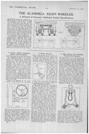
SPECIFICATION No. 283,276 bears the names of 0.D.North, P. G. Hugh and Scammell Lorries, Ltd. Lorries made in accordance with this plan are now so well known that it requires but little description to make the drawing clear. The invention lies in the fact that the rear or travelling wheels of a three-axled, articulated vehicle are duplicated and are mounted on short independent axles, each of which is pivoted at its centre to allow the wheels to follow any uneven contour of the road.
As described in the specification, the arrangement is applicable only to the trailing wheels, which are mere weight Carriers, and do not act to drive the vehicle. As the driving *heels must necessarily carry a fair proportion of the weight, the duplicated wheel arrangement would, of course, be more useful if it could be applied to them instead of, or as well as, to the trailers.
A Brake Which Contains Many Good Features.
THE brake shown in the specification,
No. 283,397, of Paul A. S. Iversen, of 25, Frederiksborggade, Copenhagen, appears to possess many novel and useful points. The main feature of the invention lies in the fact that the expander cans operates in a radial direction on the shoe instead of in a tangential direction as in most brake conetructions. Several applications of the plan are shown, but the one we have selected appears to show the invention
in its best form. The ring of spring steel faced with suitable material takes the place of the usual, shoes, and is anchored at one end and is allowed to contract on to a number of suitable stops which will ensure its clearing the drum when not in use.
There is no expander in the usual meaning of the word, as the cam takes the form of an eccentric which sets up friction between the end of the ring and the drum. This friction is sufficient to cause the, ring to tend to expand, and in doing so to cause friction between it and the drum, thereby forming a servo brake. As shown, it is only applicable to brake which is required to act in one direction only, as is the case with a front-wheel brake.
A Brake Booster.
IT is well understood that much valu
able movement of brake pedal levers is wasted in brakes as usually constructed. The necessarily low ratio of movement between the pedal lever and the leVer on the expander camshaft is employed whilst the clearance between the shoes • and the drum is
262 020 beieg, taken up. It is plain that the first part of the movement of a pedal lever might be boosted up in relation to the lover on the shaft a the cam, as the arc described by the pedal lever is necessarily a small one, and movement should be economized as far as possible.
John Alfred Prestwich, in his patent No. 282,920, describes in arrangement which is designed for the purpose of boosting up the first part of the reoVement when a brake is applied. The arrangement consists of a pedal lev6r which extends below its fulcrum as shown. Attached to its lower extremity is a second lever, which carries a roller acting upon a fixed cam. The roller, as it passes up the sloping portion of the cam, imparts an accelerated movement to the lever to which the pull rod of the brake is attached. After the roller has reached the concentric part of the cam, the movement imparted to the pull rod is normal. To make the plan plainer, we have added, in dotted lines, to the drawing the position of the second lever when it is on the concentric part of the cam. It would appear to us that, es the stress on the second lever is of a transverse nature, there may be an increased amount amount of spring when applying the brake, and this spring might nullify the advantage gained by the boosting. Efforts were made some years back in this direction, but, although some very satisfactory devices were made they met with no encouragement.
A -New Device for Washing Commercial Motors.
IN this device, one of the cylinders is
employed as a means of pumping water for the purpose of cleaning vehicles. The patentee is Henri Gamard, of Bourges, Cher, France, and the specificationis numbered 270,654. One of the sparking plugs is removed from the engine of the vehicle that is to be employed as a source of power. A pipe is then connected to the hole previously occupied by the sparking plug, and is led from there to the ,upper part of the device shown, where the pressure of air due to The compression expands the rubber bulb, which contracts to its original size at the opening of the exhaust valve on every alternate stroke of the piston,.thua turning the bulb into a diaphragm pump.
The bulb, by its return to normal after being expanded, causes a vacuum in the chamber in which it is situated; this vacuum causes water to enter, as is in(Heated by the arrow on the left and, being retained by means of a non-return valve not shown, it is exlielled at the time of its next expansion, through the opening shown on the right. This opening is also provided with a non-return valve and a hose for washing. When the engine is used for this purpose it has to run with one idle cylinder.