


PNEUMATIC TRANSMISSION.
Page 32
If you've noticed an error in this article please click here to report it so we can fix it.
A Resume,of Recently Published Patent:
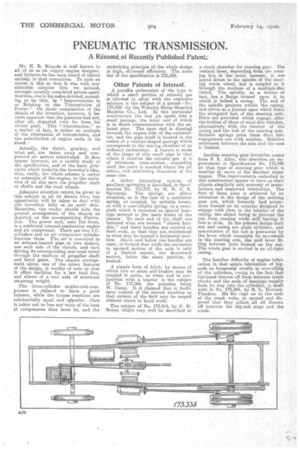
Mr. H. R. Ricardo is well known to all of us as an expert engine designer, and hitherto, he has been heard of almost entirely in that connection. To such an extent is this so that it was with considerable surprise that we noticed, amongst recently completed patent, specifications, one in his naime devoted, according to its title, to " Improvements in or Relating to the Transmission of Power." On closer examination of the details of the invention, however, it became apparent that the patentee had not, after all, departed very far from his chosen path. This "transmission," as a, matter of fact, is rather an example of the elimination of transmission, and the substitution of engine units in its stead. • Actually, the clutch, gearbox, and what not, are taken away and compressed air motors substituted. It does appear however, on a careful study of the specification and of the basic prin. ciples which underlie the inventor's idea, that, really, the whole scheme is rather an extension of the engine, to the exclusion of all else save the.propeller shaft or shafts and the road wheels,
Adequate attention cannot be given to this subject in all its details here, but opportunity will be taken to deal with this invention fully at an early date. Meantime, the reader should note the general arrangement of the chassis as depicted on the accompanying illustration. The power unit, near thd front, is a combined internal-combustion engine and air compressor. There are two I.C. cylinders and an air compressor cylinder between them. The air is conveyed in an exhaust-heated pipe to two motors, one each side of the chassis, and each driving its corresponding rear road wheel through the medium of propeller shaft and bevel gears. The chassis arrangement alone, one of the minor features of the design, is worthy of note in that it offers facilities for a low load line, and allows of a rear axle of minimum unsprung weight.
The three-cylinder engine-cum-compressor is claimed to have a good balance, while the torque reactions are substantially equal and oeposite. Care is taken not to lose any more of the heat of compression than must be, and the
underlying principle of the whole design is high, .ail-round efficiency. The num. her of the specification is 173,338.
Other Patents of Interest.
A paraffin carburetter of the type in which a. small portion of exhaust gas is -allowed to enter with the explosive mixture is the subject of a patent—No. 173,359—by the Wolseley Sheep Shearing Machine Co., Ltd. In this particular construction the fuel jet opens. into a small passage, the inner end of which is in direct communication with the exhaust pipe. The open end is directed towards the engine side of the carbureter, and the pipe itself is located in the centre of a venturi-shaped passage which corresponds to the mixing chamber of an ordinary carburetter. A feature is made of the shape of this small pipe in that where it receives the exhaust gas it is of minimum cross-section, expanding until the point is reached where the jet enters, and, continuing thereafter of the same size.
Arather interesting system of auxiliary springing is described, in Speci. fication No. 153,572, by M. H. C. E. Sainturat. The springs are either attached, es in the case of a cantilever spring, or coupled, by suitable levers, as with a semi-elliptic spring, to a crossshaft which is mounted on special bearings secured to the main frame of the Chassis. To each end of the shaft are fastened what are termed "elastic bundles," and these bundles are secured at their ends, so that they are maintained in what may be termed a horizontal position. Above and below the bundles are cams, so formed that while the resistance to upward motion of the axle is only of a limited extent, the downward motion, below the mean position, is braked.
A simple form of hitch, by means of which two or more self-binders may be coupled in series, as when and in conjunction with a tractor, is the subject of No. 173,266, the patentee being W. Camp. It is claimed that it facilitates control of the second machine so that corners of the field may be reaped without resort to hand work.
The subject of No. 173,414, by F. H. Royce, might very well be described as a shock absorber for steering gear. The vertical lever, depending from the steering box in the usual manner, is not keyed direct. to the spindle of the steering worm wheel, but is coupled to it through the medium of a multiple-disc clutch. The spindle, as a matter of fact, has a flange formed upon it to which is bolted a casing. The end of the spindle projects within the casing, and serves as a journal upon which bears the elongated hub of the steering arm. Discs are provided which engage, after the fashion of those of most disc clutches, alternatively with the interior of the 'casing and the hub of the steering arm. Suitable sprii.gs press these discs into engagement one with another. Relative movement between the arm and the casa is limited.
Another steering gear invention comes from S. E. Alley, who describes an improvement in Specification No. 173,440 on that type of steering gear which is familiar to users of the Sentinel steam wagon. The improvements embodied in this construction appear to have as their objects simplicity and economy of manufacture and improved lubrication. The first of these aims is achieved by an alteration in the design of the steering gear nut, which formerly had projectams formed on its exterior designed to engage with slots in the interior of the casing, the object being to prevent the nut from turning while still leaving it free to slide. In the present design both nut and casing are plain cylinders, and non-rotation of the nut is prevented by the lever which transmits its movement to the steering arm, the said lever fitting between jaws formed on the nut. The whole gear is carried in an oil-tight casing.
The familiar difficulty of engine lubrication in that ample lubrication of bigends so frequently results in over-oiling of the cylinders, owing to the fact that lubricant thrown off from between crank cheeks and the ends of bearings usually finds its way into the cylinders, is dealt with in No. 173,304, by R. L. HowardFlanders. He fits cups on to the ends of the crank webs, so opened and disposed that they collect all oil thrown off between the big-end steps and the crank.