


PATENTS SUMMARIZED.
Page 22
If you've noticed an error in this article please click here to report it so we can fix it.
. Another Chain-track Tractor.
Specification No.112,230, by W. G. Trethewey, concerns a chain-track tractor .and malts-furrow plough, in the construction of which several innovations are embodied. The 'ploughshares -are each attached-by several draglinks to a towing bar,' which is 'disposed at an angle
• to the axis of the tractor, so that all the ;share coupling .links are of the same length.Simplicity of operation and evenness of action aressgained by this construction, . .
The chain track is carried on two :wheels, of .which the driver 18 about -three times the diameter of the driven 's wheels 'These wheels are coupled together by radius rods;and eccentric adjustment about the axle of, the driven :wheel is provided for tensioning the chain tracks. By means of gearing operated by the engine, 'it is possible •• to lift either or, both of the fore-ends 'of the. racks, thus affording additional Convenienee when turning or when runnings on soft greund. A central front wheel Serves as .a steering 'wheel, and it • is customary 'when turning to either side to lift the fbir-e' end of the' chain track on 'that side, Safety Coupling for an Agricultural Motor.
.A coupling. of the type wherein a spring, or springs, Serves to transmit the
• drawbar. Pull is described in specification No 112,382, by R, H. Sellar. The aetoal 'corniedion to the implement is -by means of a; hook, -which is so designed that-upon the resistance to traction exceeding a predetermined amount, thus compressing-the -springs -beyond a certain limit, the hook is set free and falls Away from the implement, releasing it. As drawn the eyebolt shown to the left is coupled' to'a'sross 'bar from which two long bolts -extend. • These bolts carry, near their other end, a second crossbar with a slot lathe centre of it.. A little further USA is a third crossbar, which serves as an abutment for two springs Which surround the two bolts. Still another. crossbar serves as the abutment for the other: ends of these springs, and a
Central bolt runs from this last-named .bar and carries at its right-hand end, as seen in the drawing, a pair of links which passes through the longitudinal hole in the second crossbar, to which hole reference has already been made.A bolt at the other end of these links passes through a hook of plain rectan
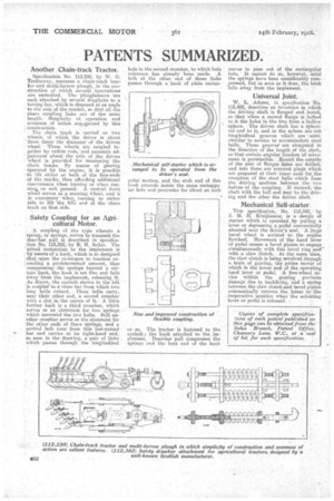
Mechanical self-starter which is arranged to be operated from the driver's seat.
?sitar 'section, and the stub end Of this hook extends inside the same rectangular hole and protrudes for about an inch
or so. The tractor is fastened to the eyebolt; the hook attached to the implement. Drawbar -pull compresses the springs and the butt end of the hook
movesto pass out of the recta,ngular hole. It cannot do so, however, until the springs have been considerably corn,pressed, but as soon as it does, the hook falls away from the implement. • s
Universal Joint.
W. L. Adams, in specification No. 112,402, describes an invention in which the driving shaft is flanged and boied, so that when a second flange is .bolted to it the holes in the two form a 'hollow sphere. -The driven shaft has a Spheri cal. end to it, and in the sphere are Cut longitudinal grooves which' are semicircular in section to accommodate steel halls. These grooves are elongated in the direction of the length of the shaft, so that certain angular freedoM• of movement.is permissible. Hound the outside of the pair of flanges holes are drilled; and into these are screwed plugs which are prepared at their inner ends for the reception of the' steel balls which form the driving' medium between the two halves of the coupling. If desired, 'the shaft with the ball end may be the drivs iug and the other the driven Alan.
Mechanical Self-starter.
This specification No 112,343,,by J. M. H. Kluijtmans, is a design of starter . which is operated by. pulling a lever or depressing a pedal conveniently situated near the driver's seat. A large bevel wheel is •sechied Ito the engine flywheel. Movement of the hand lever or pedal causes a bevel pinion to-engage simultaneously with this bevel ring -and with a'claw clutch,. At the same time, the claw clutch is being revolved through a train of gearing, the prime mover of which is the lower end of the operating hand lever or pedal. A free-wheel device within the gearing prevents damage due to backfiring, -and a Oring between the claw clutch.and bevel pinion automatically .returns the latter to the .
inoperative position when the actuating lever, or pedal is released.