


Thermally Controlled Starting Device
Page 42
If you've noticed an error in this article please click here to report it so we can fix it.
A Résumé of Patent Specifications That Have Recently Been Published.
TOcontrol the mixture strength during cold starting and the subsequent warming-un period, is the aim of an improved carburetter shown in patent No. 571.932, by Bendix Aviation Corporation. South Bend, Indiana, U.S.A
The carburetter operates, generally, on well-known lines, the improvements residing in the choking arrangements for the air supply The choke-valve (I) is of the unbalanced type, and can be manually operated in the usual manner
by wirebut is also subject' to the influenze ot a thermostat (2) located close to the exhaust system. In operation. the an flow tends to open the valve owing to its unbalance. but this is resisted by the thermostat until the exhaust temperature has risen. The marmar control can override the autoaction in ill positions, hut if it be left in its central position; where it is held by a spring-hall (3) it permits the thermostat to take control. A feature of the scheme is the provision of a fastidling cam (4) which opens the main throttle slightly during the time the choke-valvt is closed.. An automatic valve (5) in the valve ensures that a small quantity of air may get through at all thnes
A PISTON FOR HYDRAULIC BRAKES
ONE of the problems met with in the design of hydraulic-brake cupwashers is that of a momentary subpressure; this may cause a "let-go ' of the self-scaling lip and permit fluid to pass. lo provide an effective two-way seal is the object of an improved piston arrangement shown in patent No. 5'71.910 by N Nawton, Newton and Bennett Works. Vaietta Road, London, W3
The drawing shows an expander unit as used between the shoes of a brake mechanism. Two opposed pistons are
shown each illustrating a particular constructien. although the principle is the same Each piston contains a pair of face-to-face cup-washers which, in use cause the intervening space to become filled with fluid under working pressure The two washers are held span by a tubular perforated spacing collar
The two washers and the trapped fluid move in unison and form the complete piston, this cannot leak in either direction because one or the other of the washers must be moving in a selfsealing sense however momentary the applied sub-pressure. The right-hand end of the cylinder shows a variation of the scheme, in this case the washers seal only on their outer diameter, the central bore being closed by clamping.
TYRE TESTING BY HIGHFREQUENCY VIBRATIONS THE difficulties of testing tyre covers for hidden cracks, air bubbles and other faults are outlined in patent No. 571,817 by the Wingfoot Corporation, Akron, Ohio, U.S.A. Many schemes have been tried, including X-rays, but none has proved satisfactory, and the patent proceeds to describe a new method employing supersonic vibrations. Vibrations of this nature, having a frequency of from 10,000 to 50,000
eye es per second, possess the property of being easily impeded by the slightest resilient medium, such as an air bubble, whereas they pass easily through incompressible substances.
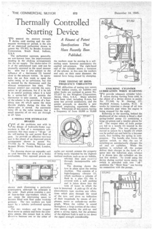
The drawing shows the tyre in place upon the testing machine. This consists of a high-frequency vibrator (1), which oscillates a column of fluid in a pipe (2); this is covered with a soft packing and is taken down into the tank of water in which the tyre is immersed. A pick-up (3) of the piezo-electric type reseives any vibrations which pass through the tread of the tyre. and gives an indication of their magnitude by means of earphones, meter or cathode-ray oscillograph. When the rubber is sound throughout, a large portion of the vibration energy reaches the pick-up and gives a strong signal, but the presence of the slightest fault is said to cut down the signal strength considerably. ENSURING CYLINDER LUBRICATION WHEN STARTING
TOprovide adequate cylinder lubrication during starting from cold, is the object of a device shown in patent No. 571,940, by W. Dewing. 157, Mayfield Avenue, London, N.12. It works by injecting a charge of oil into the induction pipe when the engine is
being stopped for the night.
Referring to the Clawing, behind the dashboard of the vehicle is fitted a dual spring-loaded pump (1) containing a large air-piston and a smaller piston for oil. The output sides of both pumps are led to a nozzle (2) located in the induction pipe. The two pistons are moved in unison by a handle (3) which can be pulled out and held by a bayonet catch, thus holding the spring in compression. The handle also forms the ignition switch, so that the act of switching-on automatically charges the oil and air cylinders. When the ignition is switched off, the pumps deliver their charges in the form of a , spray into the induction pipe, whence it is drawn into the cylinders on the last few strokes. To avoid using the device during normal warm starts, the switch is provided with two " off " positions the "Short Stop" one having no connection with the pumps.