


A NEW ENGINE LUBRICATION SYSTEM.
Page 30
If you've noticed an error in this article please click here to report it so we can fix it.
A Résumé of Recently Published Patents.
A week or so ago we referred in this page to the fact that, out of three patent specifications dealing with agricultural tractors, two were of Continental origin. Now, in selecting these patents, the whole of the specifications completed each week are carefully passed under review, and from them are selected a few, generally half-a-dozen or more, which appear to be of particular interest to readers of this journal. Rarely are the names of the patentees glanced at; the subject matter only is considered, and, it was not until this week's selection of specifications had been brought to the office and examined that the following curious fact was discovered, that, out of eight, no fewer than six are Continental, the remainder being British. Of the six, four are French, one German, and one Swiss.
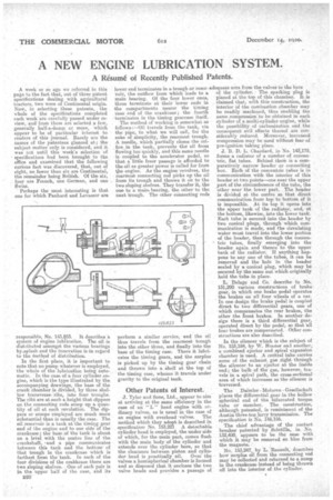
Perhaps the most interesting is that one for which Panhard and Levassor are responsible, No. 143,853. It describes a system of engine lubrication. The oil is distributed amongst the various bearings by.splash and the innovation is-in regard to the Method of distribution.
In the first place, it is important to note that no pump whatever is employed, the whole of the lubrication being automatic. In the case of a few cylinder engine, which is the type illustrated by the accompanying drawings, the base of the crank chamber is divided, by three shallow transverse, ribs, into four troughs. The rib § are at such a height that dippers on the connecting rods scoop up a quantity of oil at each revolution. The dippers or scoops employed are much more substantial than is usually the case. The oil reservoir is a tank at the timing gear end of the engine and to one side of the crankcase; the base of the tank is about on a leVel with the centre line of the crankshaft, and a pipe communicates between this tank and the bottom of that trough in the crankcase which is farthest from the 'tank. In each of the four divisions of the crankcase there are two sloping shelves. , One of each pair is in the upper half of the case, and its B20 lower end' terminates in a trough or reservoir, the outflow from which leads to a main bearing. Of the four lower ones, three terminate at their lower ends in the -compartments nearer the timing case end of the crankcase ; the fourth terminates in the timing gearcase The method of working is somewhat as follows a—Oil travels from the tank, via the pipe, to what we will call, for the sake of simplicity, the rearmost trough. A needle, which partially closes the orifice..in the tank, prevents the' oil from flowing too quickly, and this same needle is coupled to the accelerator pedal, so that a little freer passage is afforded to the oil as greater power is called for from the engine. As the enginsrevolves, the rearmost connecting rod picks up the oil from its trough and throws it on to the two sloping shelves. They transfer it, the one to a main. bearing, the other•to the next trough. The other connecting rods
perform a similar service, and the oil thus travels from the rearmost trough into the other three, and finally into -the base of the timing case. There it lubricates the timing gears, and the sprpius is picked up by the timing gear chain and thrown into a Shelf at the top of the timing case, whence it travels under gravity to the original tank.
Other Patents of Interest.
J. Tyler and Sons, Ltd., appear to aim at arriving at the same efficiency in the case of an " L " head engine with ordinary valves, as is usual in the case of an engine with overhead .valves. The method which they adopt is described in specification No. 153,221 A detachable cylinder head is employed, the under side of which, for the main part, comes flush with the main body of the cylinder and extends over the cylinder bore, so that the clearance between piston and cylin dee head is practically nil. Over the valves a hemispherical chamber is formed and so disposed that it encloses the two valve heads and provides a passage of
adequate area from the valves to the bore of the cylinder. • The sparking Plug is placed at the top of this chamber. It is . claimed that, with this construction, the interior of the combustion .chamber may be readily machined, thus enabling the same compres•sion'to be obtained in each cylinder of a multi-cylinder engine, while the passibility of carbonization and the 'consequent evil effects thereof are considerably reduced. Moreover, increased compressien may be used without fear•of pre-ignition taking place.
J. B. D. L. Chardard, in No. 143,179, forms a radiator of a number of concentric, flat tubes. Behind them is a comparatively narrow header or connecting box. Each of the concentric tubes is in communication with the interior of this header at two points—one neat the upper _part of the eitcumference of the tube, the other near the lower part. The header is divided at the centre so that direct communication from top to bottom of it is impossible. At, its top it opens into the upper tank of the radiator, and, at the bottom, likewise, into the rower tank. Each tube is secured into the header by two conical plugs, through which cowmunitation is made, and the circulating water must. travel into the lower portion of the header, then through the concentric tubes, finally emerging into the header again and thence to the upper tank of the radiator. If anything happens to any one of the tubes, it can be removed and the hole in the header sealed by a-conical plug, which may be secured by the same nut which originally held the tube in place.
L. Delage and Co. describe in No. • 131,290 various constructions of brake gear, in which one brake pedal operates the brakes on all four wheels of a car. In one design the brake pedal is coupled direct to two differential gears, one of which compensates the rear brakes, the other the front brakes. In another design there is a third differential gear, • operated direct by the pedal, se that all four brakes are compensated. Other constructions are also described.
In the silencer which is the subject of No. 153,184, by W. Reuter and another, a' combined ejector and spiral expansion chamber is used. A central tube carries some ofthe exhaust gas right through the silencer, to an ejector at the inside end; the bulk of the gas, however, tra
vels in a spiral path, the cross-sectional
area of which increases as the silencer is traversed.
The Daimler Motoren Gesellschaft places the differential gear in the hollow spheridal end of the bifurcated torque tube or member. The construction, although patented, is reminiscent of the Austin three-ton lorry transmission. The specification is No. 146,156.
The chief advantage of the contact breaker patented by Scintilla, in. N. 132,499, appears to be the ease with which it may be removed en bloc from the magneto. '
No. 153,247, by L. TRenault, describes how surplus oil from the connecting rod may be collected and returned to a sump in the crankcase instead of being thrown off into the interior of the cylinder.