


A Novel Method of Shock Absorption.
Page 21
If you've noticed an error in this article please click here to report it so we can fix it.
nNE of our readers sent us recently a sketch and descrip
tion of an interesting type of springing, which would appear to possess many possibilities, particularly as regards the absorption of shock in the bodies of passenger and other vehicles. It migibt possibly be employed. for the springing of chassis, but we do not think it would be quite so suitable in this connection.
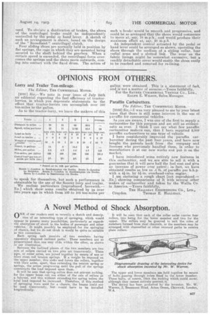
• Each spring unit consists of. two members having oppositely disposed inclined paths. These members are so proportioned that one may slide within the other, as shown in our illustration.
Between the inclined planes -of .the two members are two sets of rollers carried on two pins set transversely.. These pins, or roller axles, are joined together by means of ene or more stout coil tension springs. If a weight be imposed on the upper member, this sinks and forces the rollers, together with their axles, apart, thus extending, the tension spring or springs, the action progressing until the pull Of the springs counteracts the load imposed upon them. It will be seen that spring., action does not prevent rocking, for the upper beam can use either of the sets of rollers as a fulcrum, and this without extending the' spring unless the total load imposed be increased. Thezefore, if this method of springing were used for is chassis, the beams lould not be used transversely, but-would have to be installed longitudinally. It will be seen that each of the roller axles carries four rollers, two being for the lower member and two for the , upper. The' rollers may be grooved to suit the sides of members formed from steel clia.nneIs, 'or the members may be arranged with channelled or other recessed paths to receive plain rollers.
The upper and lower Members m:e held together by means of bolts passing through tubes fixed to the lower member. These bolts, of course, limit the rocking which could occur, although they cannot entirely prevent it. The device has been protected b the inventor, Mr. W. Warren, 3, Beaumont Road Acton Green, Chiswick, London, W.4.