


Patents Completed.
Page 22
If you've noticed an error in this article please click here to report it so we can fix it.
Complete specifications of the following patents will be sent to any address in the United Kingdom upon receipt of eightpence per copy at the Sale Branch, Patent Office, Holborn, W.C.
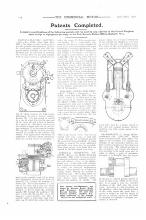
MAGNETO-ELECTRIC IGNITION . —Hail.—No. 12,286, dated 25th May, 1909.—The object of this invention is to provide a simple dual system of ignition for small-power engines and also improved means whereby the two contact breakers may be advanced or retarded. The bearing plate (1) has cast integral with its upper portion a cylindrical cas hig (2) which contains the nigh-tension distributor (3) and a battery contactbreaker (4). The last-named is efirrieci by a cap (5) which fits into the open end of the casing (2) and is held in position by a spring (6); this spring conveys the low-tension current from one of the battery terminals (7) to the contact-breaker, The cap 15) is capable of being partially rotated to provide for the advance and retard. The high-tension distributor (3) comprises a vulcanite rotary distributor ring ill), having around its periphery a
semi-circular metallic band (12) to which the high-tension current is led, from the terminal (13), through the medium of a feeder (14 The rotary member (11) carries at its outer end a cam (17) which actuates the contact-breaker ; the rotary member is driven from the armature gpindle ,(18) through the medium of the sper wheels (19, 20 and 21). 31 is the magneto contact-breaker, and this is carried within a removable, and rotatable. cap 32 which fits within the outer end of the casing ,3). This magneto contact-breaker (31) is mechanically connected to the battery contact-breaker (4) so as to be .synehronized therewith when advancing or retarding the ignition. For
this purpose ii spi 34) is employed ; this spindle is connected, at one end, to the magneto circuit-breaker cap (32) by a link (35), while at the other end it is connected with the battery circuitbreaker cap (5) by means of a link 36 and curved arm 37 to which one end of the link (38) is joined, whilst the other end of the last-named link is pivoted to the cap (5). W hen the arra (37) is actuated the caps (5 and 32) of both contact-breakers are caused to be partially rotated simultaneously. thus advancing, or retarding the two systems. In order to compensate finthe lag of the coil system the arrangement of the links and levers is such that a greater movement is given to the battery contact-breaker than to that of the magneto.
ANTI-SKID COVERS FOR PNEUMATIC TIRES. — Beaumont. — No, 16,664. dated 16th July, 1909.—This invention relates to anti-skid tires of the type described in Patent. Specification No. 28,517 of 1909 wherein the tread is comparatively wide Slid is formed with sharp edges which are held in close. mutact with the surface of the road. The object of the present invention is to provide a cover having similar sharp edges and which can be fitted. over the tire
when it has become worn. The cover is formed with wire rings at each side which, when the Lire is inflated, prevent the cover from being dislodged. In order further to support the cover, additional adjustable wire rings may be provided; these rings engage with hooks that are carried hiy the first-named wire rings.
INTERNAL COMBUSTION ENGINES.—Royce.—No. 20.063, dated 2nd September, 1909.—This invention relates to internal-combustion engines having inlet and exhaust valves of the slidingpiston type. At the head of the cylinder, two cvlindrical extensions are provided, in which are arranged reciprocating pistons. These. pistons are actuated by rocking shafts, through the medium of connecting rods. The rocking shafts are actuated by vertical rods which are in turn driven from half-time shafts, through the medium of cranks. The pistons within the cylindrical extensions of the cylinder are adapted to cover and to uncover the inlet and exhaust ports. The object of this arrangement of valve gear is to maintain the inlet and exhaust parts fully open for a longer period of the inlet mid exhaust strokes, thereby enabling very high engine speeds to be obtained.
CRANKSHAFTS.—F. Krupp Aktiengesellschaft.—No. 2,2871910. Dated under Convention 27th April, 1909.—The object of this invention is to increasethe strength of the connection between the pins or reduced portions of the crank and the crank arms. The reduced portions of the crankshaft and cranks are shrunk into the holes in the crank arms, and, in order to obtain a joint of maximum strength, it is desirable that the length of the pin or reduced portion should he equal to that of the width of the crank arm. It is usual to sink the rounded shoulders of the shaft into the crank arms. According to this invention, at the shoulder, where the reduced portion of the crank enters the crank arm, a groove is formed so that the length of the pin or reduced portion of the shaft is increased and thereby a stronger connection is obtained,