


Hygienic Refuse Collection
Page 60
If you've noticed an error in this article please click here to report it so we can fix it.
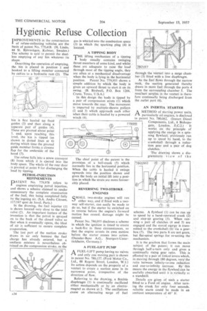
IMPROVEMENTS in the construction 1 of refuse-collecting vehicles are the basis of patent No. 779,418. (H. Linde, 44 St. Bjarnvagen, -Kalmar, Sweden.) The scheme is said to permit the dustless emptying of any bin whatever its shape.
Describing the operation of emptying, the bin is placed in position 1 and hooked to a lifting member connected by cables to a hydraulic ram (2)". The bin is first hauled up fixed guides (3) and then along a separate pair of guides (4). These are pivoted about point 5, and, upon reaching this level, the bin is tipped (as shown in dotted lines at 6) during which time the pivoted guide member form3 a closure flap for the underside of the hood (7).
The refuse falls into a screw conveyor (8) from which it is. ejected into the body space. The whole of the rear door . is pivoted at point 9 for discharging the load by tipping.
PETROL-INJECTION
REFINEMENTS
PATENT No. 779,978 refers to engines employing petrol injection, and shows a scheme claimed to render unnecessary thecomplete atomization of the fuel, this being completed fully by the ingoing air. (S.A. Andre Citroen, 117/167 quai de Javel, Paris.)
In the drawing, the fuel injector (1) is shown located very close to the inlet valve (2). An important feature of the invention is that the petrol is sprayed on to the back of the closed valve so that when it eventually opens, the blast of air is sufficient to ensure complete evaporation.
The last part of the suction stroke draws in air only because the fuel charge has already entered, but a uniform mixture is nevertheless obtained on the compression stroke, as the gas is whirled into the combustion space (3) in which the sparking plug (4) is located.
A TIPPING BODY
THE lifting mechanism of a tipping body usually contains swinging thrust members of some kind, and whilst these arc adequate to raise the load through most of the tipping angle, they are often at a mechanical disadvantage when the body is lying in the horizontal position. Patent No. 779,935 shows a simple addition by which the body is given an upward thrust to start it on its swing. (B. Birdwell, P.O. Box 1266, Crane, Texas, U.S.A.)
In this design the body. is tipped by a pair of compression struts (1) which move towards the rear. The movement is imparted by multiple-sheave pulleys (2 and 3) which approach each other when their cable is hauled by a powered winch (4).
The chief point of the patent is the provision of a bell-crank (5) which normally lies in the horizontal position. When the cable is hauled it swings upwards into the position shown and gives the body an initial lift intci a position in which the struts are more favourably placed.
REVERSING TWO-STROKE ENGINES
SMALL two-stroke engines will run either way, and if fitted with a twoway self-starter, can easily be made to do so, but if the starter be switched on in reverse before the engine's forward motion has ceased, damage might he caused.
Patent No. 780,055 discloses a scheme in which the ignition is timed to create a back-fire in these circumstances, so that the engine arrests its own motion before the starter comes into action. (Daimler-Benz A.G., Stuttgart-UntertUrkheim, Germany.) ' A FUEL-LIFT PUMP
AFUEL-L1FT pump having no valves and only one moving part is shown in patent No. 780,157. (Ford Motor Co, Ltd., 88 Regent Street, London, W.1.) Its action-depends on the property of a venturi to create a suction zone in its narrowest point, irrespective of the direction of flow.
Referring to the drawing, a flexible diaphragm (1) is continually oscillated either mechanical' or by an electromagnet as shown at 2. The oscillations cause an alternating surge of fuel through the venturi into a surge cham ber (3) fitted with a free diaphragm.
As the fuel flows through the narrow neck, the suction generated thereby draws in more fuel through the ports 4 from the surrounding chamber 5. The resultant surplus in the venturi is therefore continually being discharged from the outlet port (6)..
AN INERTIA STARTER
AMETHOD of starting power units, particularly oil engines, is disclosed in patent No. 780,062. (Tristan Diesel Components, Ltd., 6 Bishopsgate, London, E.C.2.) It works on the principle of applying .the energy in a spinning flywheel, previously run up to speed by hand, to the crankshaft through a reduction gear and a pair of dog
clutches.
The drawing shows a diagrammatic view of the scheme. A flywheel (1) can be run up to speed by a hand-operated crank (2) and step-up gearing (3). When running • a pair of clutches (4 and 5) are engaged and the stored energy is transmitted to the crankshaft (6) via a gearbox (7). The two parts 8 are not gears, but flat-spiral springs for re-setting the mechanism.
It is the gearbox that forms the main subject of the patent; it can move through half-a-turn only and gives a continually rising gear ratio. This is effected by a pair of linked levers-which, in moving through 180 degrees, vary the ratio between infinity-to-one reduction and one-to-infinity increase. By ' this means the energy in the flywheel ran be usefully absorbed until it is virtually at a standstill.
Details are given of such a starter fitted to a Ford oil engine. After turning the crank for only four seconds. reliable starts could be made in an ambient temperature of 40° F.