


A Suction-assisted
Page 48
If you've noticed an error in this article please click here to report it so we can fix it.
Hydraulic Brake System
A Résumé of Recently Published Patent Specifications
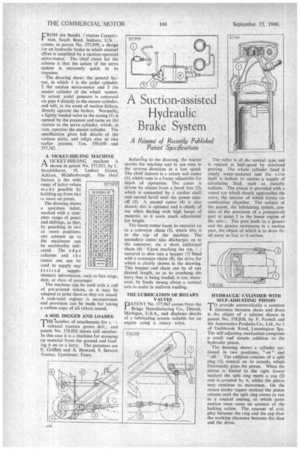
FROM the Bendix /.viation Corporation, South Bend, Indiana, U.S..... comes, in patent No. 577,999, a design for an hydraulic brake in which manual effort is amplified by a suction-operated servo-motor. The chief claim for the scheme is that the action of the servo system is extremely quick in its response.
The drawing shows the general layout, in which 1 is the pedal cylinder. 2 the suction servo-motor and 3 the master cylinder of the wheel system. In action, pedal pressure is conveyed via pipe 4 directly to the master cylinder, and will, in the event of suction failure, directly operate the brakes. Normally, a lightly loaded valve in the casing (5) is opened by the pressure and turns on the: suction to the servo cylinder, which, in t urn, operates the master cylinder. The specification gives full details of the various parts, and refers also to two earlier patents, rios. 550,450 and 557,762.
A TICKET-ISSUING MACHINE A TICKET-ISSU1NG machine is IA shown in patent No. 577.917, by I..
Brock lehu rst, 10, Lodore Grove, Acklain, Middlesbrough. The chief feature is the wide range of ticket values made possible by building up from two ot more set prices, The drawing shows a specimen ticket, marked with a complete range of pence and shillings, so that, by punching in two or more positions, any amount up to the maximum can be unalterably indicated. The edge columns and t h e centre one can be used to supply any
de s i red supplementary information, such as fare stage, date, or class of passenger.
The machine can be used with a roll of pre-printed tickets, or it may be adapted to print them as they are issued. A cash-total register is incorporated, and provision can be made for taking a carbon copy of all tickets issued.
A SOIL DIGGER AND LOADER
THEenumber of attachments for cultural tractors grows daily, and patent No. 578,035 shows still another. In this case it is a machine for scooping up material from the ground and loading it on to a lorry. The patentees are E. Griffith and A. Howard, 9, Stewart Avenue, Upminster, Essex.
Referring to the drawing, the tractor carries the machine and in use runs in the reverse direction at a low speed. The chief feature is a rotary soil cutter (I), which runs in a frame adjustable for depth of operation. The cutter is driven by chains from a,,bevel box (2), which is connected by a cardan shaft and second bevel with the power takeoff (3). A second cutter (4) is also shown; this is optional and is chiefly of use when dealing with high heaps of material, as it saves much adjustment for height.
The lower cutter loads its material en to a conveyor chain (5), which lifts it to the top of the machine. The secondary cutter also discharges on to the conveyor, via a short additional chain (6). Upon reaching the top, t material is shot into a hopper (7) fitted with a conveyor chain (8), the drive for which is clearly shown in the drawing. This hopper and chain can be of any desired length, so as to overhang the lorry that is being loaded; it can, moreover, be freely swung about a vertical axis to assist in uniform loading.
THE LUBRICATION OF ROTARY VALVES
DATENT No. 577,967 comes from the
Briggs Manufacturing Co., Detroit, Michigan, U.S.A., and discloses details of a lubricating system suitable for an engine using a rotary valve. The valve is of the conical type and is rotated at half-speed by overhead gearing. The whole cylinder head is amply water-jacketed and the wive itself is hollow to receive a supply of circulating fluid, such as metallic sodium. The piston is provided with a coned top which closely approaches the valve, the interior of which fonns the combustion chamber. The subject of the patent, the lubricating system, consists of the provision of a pressure-oil port at point 1 in the lower region of the valv:. The port leads to a groove and the groove terminates in a suction port, the object of which is to draw thr oil away as fast as it arrives.
HYDRAULIC CYLINDER WITH SELF-ADJUSTING PISTON
T°provide automatically a constant clearance between shoes and drum is the object of a scheme shown in patent No. 578,038, by F. Parnell and the Automotive Products Co., Ltd., bo:h of Tach brook Road, Leamington Spa. The self-adjusting mechanism comprises a small and simple additioh to the hydraulic piston.
The drawing shows a cylinder sectioned in two positions, on" and "off." The addition consists of a split ring (1), conical on its outside, which frictionally grips the piston. When the piston is forced to the right (lower section) the split ring meets a cap (2) and is arrested by it, whilst the piston may continue its movement. On the return stroke (upper section) the piston returns until the split ring comes to rest in a conical seating, at which point motion must cease on account of the locking action. The amount of endplay between the ring and the cap fixes the working clearance between the shoe and the drum.