


AN AID TO GEAR-CHANGING.
Page 68
If you've noticed an error in this article please click here to report it so we can fix it.
A Résumé of Recently Published Patent Specifications.
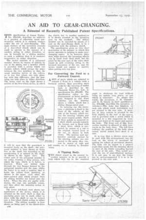
MEM specification of James Farley, No. 275,530, describes an addition to a gearbox of otherwise usual construction which, it is claimed, renders easier the net of gear-changing. The main feature of the invention consists of a free-wheel dutch which can be made to operate in the manner of a ratchet, acting in either direction, or can be brought by a sliding member to such a pOition. that it is rendered inoperative in either direction: The device consists of -a polygonal member driven by means of splines by one of the shafts, and a member which is provided with a recess which can contain rollers, which occupy the space between the two members so that the usual jamming action of the rollers, as in any free wheel, can take place, but with this difference, that the jamming can take place in either direction. The lower view on the right -shows a section of the free-wheel device, in whieh it will be seen that the gearwheel is mounted freely on the shaft; the polygonal member is here shown as tieing free on the shaft, but according to the specification it is splined to the shaft, as shown in the upper view. The centre part of -the polygonal member is cut away, forming a sleep groove, into which the cage, which is in halves, is inserted. Holes are drilled right through the two flanges formed by the polygonal member and the cage, whilst the latter is in such a position that it holds the rollers from jamming, as shown in the upper view, when the taper-pointed pins which project from the sliding member are forced into the holes. When , the pins are partly withdrawn, the cage can partially rotate, and thus allow the jamming action to take place.
The lower left-hand view shows one application of the device, where it is situated on the main shaft so that the operating gears can be made either to drive with the shaft or can be turned into a free-wheel clutch Acting in either direction. The sliding member is here shown as being part of the-direct-drive
dog clutch, but in another application it is shown situated in the operating gear on the layshaft. The sliding member can be operated by means of a CAM on the gear-change shaft, or by a connection. with the Ordinaryclutch.
The specification gives DO -very clear description of the manner in which this device operates in helping to make gearchanging easier. It is, however, plain ;that, when desired, the operating wheels can be freed from their shaft, but the gears 'on the rear part of the -main shaft ,would be still revolving owing to the forward movement of the car, and the device would not appear to operate when getting into top gear.
For Converting the Ford to a Forward Control.
A SET of parts which are adapted to convert a Ford to a vehicle with a forward control, thus providing more room for the carrying of useful
lead, is described by the Chaseside Motor .Co., Ltd., in specification No. 270,397. The specification refers to the arrangement as being particularly designed to suit Ford vehicles, yet the drawing shoWs a vehicle which has a sliding change-speed gear.
In carrying out the.invention, a platform is fixed to.the front of the vehicle, at the side of the bonnet, which carries the steering column and the usual control pedals. Each of these pedals is mounted on a shaft which extends towards the bonnet, and is fitted with a short lever, which is cotneeted by means of a rod to the original control lever of the car, as shown in both Tk'iVs. The ignition and carburetter controls carried by the steering column are connected to the parts they control by means of rods and bell cranks, or, if desired, by Bowden wires.
POLYGONA£ M5195(4) A Tipping Body.
TEE Object aimed in the present invention appears to be to provide a body which will tip to the required angle to discharge its load without using an unduly long screw, or one
which is telescopic. To . obtain this result, the inventors, J. H. Chandler and G. E. Lloyd, in their specification No. 275,.:369., -describes . the -invention £18 follows :—The body has brackets on each side which tench downwards and are pivoted to the rear axle.. -A mem-her of deep section is pivoted to the 'body slightly in the rear of the centre, and is provided with a screw which is mounted in a lint supported by trunnions and bears at its upper end against the body. The. front end of this deepsection member is allowed to slide rearwards as thebody rises. The full lines indicate the position of the body when raised, whilst dotted lines show it at rest.
It is true that a shorter screw may be used with this arrangement; but the load on the screw is increased hj making its sphere of movement shorter. The body can be . tipped to a greater angle than usual, but the drawing shows no part of the frame extending beyond the rear of the axle. This would prevent the use of semi-elliptical springs. It is not easy to see how the frame can be spring-sup-ported if it is to be pivoted to the tear axle.