


A NEWCOMER TO DEAL WITH TON-LOADS.
Page 19
If you've noticed an error in this article please click here to report it so we can fix it.
A New Production from a Well-known Midland Factory. The Use of an Overheathvalve Engine with an Overhead Camshaft.
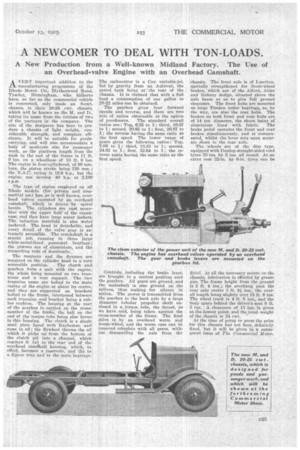
AVERY important addition to the manufacturing programme of the Rhode Motor Ca., Blytheswood Road, TyscIey, Birmingham, 'who hitherto have, so far as the commercial vehicle Is concerned, only made an 8-cwt. chassis, is their 20-25 cwt. chassis, which will be known as the M. and D.. taking its name from the initials of two of the partners in the company. The aim of the designers has been to produce a chassis of light weight, considerable strength, and complete efli. ciency. It will be suitable for goodscarrying, and will also accommodate a body of moderate size for passenger work, as the platform length from the dash to the end of the frame is 11 ft. 9 ins, on a wheelbase of 10 ft. 6 ins. Theengine is four-cyliudered, of 80 mm. bore, the piston stroke being 120 mm. ; the R.A.C. rating is 15.9 h.p., but the engine can develop 40 h.p. at 2,100 r.p.m.
The type of engine en4doyed on all Rhode models (for private and commercial use) has, as ia well known, overhead valves operated by an overhead. camshaft: which is driven 'by spiral bevels. The cylinders are cast monobloc with the Upper half of the crankcase, and they have large water jackets. The induction manifold is also water, jacketed. The head is detachable, and every detail of the valve gear is extremely accessible. The crankshaft is a sturdy job, running in three large white-metal-lined gunmetal bearings ; the pistons are of aluminium, and the connecting rods of duralumln.
The magneto and the dynamo are mounted on the cylinder head in a very. accessible position. The clutch and gearbox form a unit with the engine, the whole being mounted on two trunnions and a rear support. The two trunnion arms are bolted to the main casing of the engine at about its centre, and they are simported on brackets bolted to the frame, interposed between each trunnion and bracket being a rubber cushion. The housing at the rear of the gearbox is carried on the crossmember of the frame, the ball on the end of the torque tube being also borne in this housing. The clutch is a single steel plate faced with Raybestos, and runs in oil ; the flywheel throws the oil which it picks up from the bottom of the clutch pit into a channel, which conveys it (a) to the rear end of the overhead cam4haft housing, which, in effect, becomes a reservoir, and (h) to a dipper tray and to the main bearings. The carburetter is a Cox variable-jet, fed by gravity from an Autovac, the petrol tank being at the rear of the chassis. It is claimed that with a full load a consumption of one gallon to 20-22 miles can be obtained.
The gearbox gives four forward speeds and reverse, and there are two sets of ratios obtainable at the option
of purchasers. The standard overall ratios are : Top, 6.25 to 1; third, 10.87 to 1; second, 20.85 to 1; first, 26.87 to 1; the reverse having the same ratio as the first speed. The lower range of gears gives the following ratios : Top, 7.66 to 1; third, 13.33 to 1; second, 24.82 to 1; first, 32.94 to 1; the reverse again having the same ratio as the first, speed.
Controls, including the brake lever, are brought to a central position over the gearbox. All gears are ground, and the mainshaft is also ground on the splines, thus making for silence in action. The power is transmitted from the gearbox to the back axle by a large diameter tubular 'propeller shaft enclosed in a _torque tube, the thrust, as we have said, being taken against the cross-member of the frame. The final drive is by an overhead worm and worm-wheel, and the worm case can be removed cdmplete with all gears, without dismantling the axle from the chassis. The front axle is of I-section, specially strengthened for front-wheel brakes, which are of the Alford, Alder and Rubury design, situated above the axle beam so as to give full ground clearance. The front hubs are mounted on large Timken roller bearings, as, by the way, are also the rear hubs. The brakes on both front and rear hubs are of 14 ins. diameter, the shoes being of aluminium lined with fabric. The brake pedal operates the front and rear brakes simultaneously, and is compensated, whilst the lever acts upon separate shoes in the rear axle.
The wheels are of the disc type, equipped with Dunlop straight-sided cord tyres 33 ins. by 5 ins, all round. At an extra cost 32-in. by 6-in. tyres can be
fitted. At all the necessary points on the chassis, lubrication is effected by grease gun. The frame height from the ground is 2 ft. 4 ins.; the overhang past the rear axle centre 3 ft. 94 ins., tho overall length being slightly over 15 ft. 9 ins. The wheel track is 4 ft. 8 ins., and the body space behind the driver's seat 8 ft. 3 ins. A clearance of 11 ins, is given at the lowest point, and the total weight of the chassis is 24 cwt.
At the time of going to press the price for this chassis has not been, definitely fixed, but it will be given in a subsequent issue of The Commercial Motor.