


A SELF-LOADING LORRY.
Page 28
If you've noticed an error in this article please click here to report it so we can fix it.
A Résumé of Recently Published Patents.
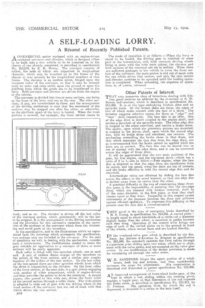
ACOMMERCIAL motor equipped with an engine-driven combined conveyor and elevator, which is designed either to be built into a new vehicle or to be mounted on to the chassis of one already completed, is described in. specification No. 213,514, by E. H. Haney. The conveyor consists of rollers, the ends of which are supported in longitudinal channels, which may be mounted on to the frame of the chassis or may actually be the longitudinal members of that frame. The elevator is an endless apron, hinged upon the rearmost roller of the conveyor, so that it may he lowered until its outer end rests either upon the ground or upon the platform from which the goods are to be transferred to the lorry. Both conveyor and elevator are driven from the engine of tire vehicle.
The conveyor is divided into two or more sections, one being at the front of the lorry and one at the rear. The other sections, if any, are intermediate to these, and the arrangement, of the driving mechanism is such that the movement of the sections may be stopped one after the other, or otherwise, as the platform space of the lorry is loaded. When the front portion is covered, for example, the front section ceases to 'uric, and so on. The elevator is driven off the last roller of the rearmost section, which, presumably, will be the last to be stopped. It is the arrangement of the driving mechanism and the provision for this successive cessation of the operation of the portions of the conveyor which form the interest
ing and novel ports of the invention. .
In the specification, and in the illustrations which we reproduced from the drawings which accompany the specification, two sections only are included in the conveyor. For the sake of simplicity we will, in dealing with the mechanism, consider euch a construction. The modifications needed to make the gear suitable. for application to a conveyor of three or more sections -will be easily apparent. Each roller is fitted with two sprocket wheels, one at each end. A pair of endless chains engage all the sprockets on the rollers of the front section, and a similar pair couples together all the rollers of the rear section. On the last roller of the last-named there are other sprocket wheels from which the drive is transmitted to the elevator. On the front roller of the front section, at the near side, is a spur pinion engaging with another of wider proportions, which is engine-driven, and thus provides the power to drive the conveyor. A second pinion, also geared to this wide one; drives the front roller of the second section throug,h a roller chain. The wide pinion is adapted to slide out of gear with the driving wheel of the front section of the conveyor, bat not out of mesh with that which drives the rear section.
„I344 The mode of operation is as follows :—When the lorry is • about to be loaded, the driving gear is clutched to some part of the :transmission, and, both conveyor driving wheels being in mesh withthe wide maih pinion, the elevator and both sections of the conveyor are set in motion. When there are sufficient packages in the vehicle to cover the front section of the conveyor, the main pinion is slid out of mesh with the one which drives that section, and only the rear section and elevator continue to be operated until the loading operation is completed. When unloading, the sequence of operas tires is, of course, reversed.
Other Patents of Interest.
THAT very numerous class of inventions dealing with fric tion gears receives an addition by the invention of E. W. Bow-en an&another, which is described in specification No. 213,303. It is-of the type embodying friction discs and an epicyclic train. Of the former there are three, the edges of two of which make contact, with the face of a third. The inventor suggests selective names for these as "edge" and "'face" discs respectively. The face disc is an idler. One of the edge dices is direct coupled to the engine shaft, and carries a sunwheel of the epicyclic train. The other edge disc is coupled to the other sunwheel, and carries a brake drum. The spider, upon which the planetary pinions are mounted, is coupled to the driven shaft, upon which the second edge disc, with its brake drum and sunwheel, can revolve. The, mechanism controlling the brake shoes in that drum, and that which separates the face disc from the edge discs, are so interconneoted that the brake cannot be applied while the discs are in contact. The face disc can be moved into or out of contact with the edge discs, and it can be traversed across the edges of those discs.
It will be appreciated that the two main positions of the gear, for free engine, and the top-speed drive—which has a ratio of 2 to 1—are as follow :—Free engine, when the face disc is disposed so that the edge discs are ,equidistant from its centre, and top speed, when the discs are out of contact, and the brake effective to hold the second edge disc and its sun wheel.
Intermediate ratios are obtained by sliding the face disc across the others in the usual mariner, so that one edge disc is farther away from its centre than the other. A practical difficulty in the way of constructing these threedisc gears is the impossibility of ensuring that the two-edge discs, which are rimmed with friction material, shall be of the same diameter, in the first place, or that they shall remain equal as they wear. Inequality in this respect causes unevenness of the pressure between the discs and -militates against efficient operation. To overcome t•his difficulty in the present case the face disc is swivel-mounted.
VERY novel is the type of emergency brake described by . H. S. Young, in specification No. 213,381. A curved plate— in length equal to about tyro:thirds of a circle—of a diameter slightly larger than the wheel, is mounted in guides beneath each rear wing. Operation of the control lever brings one edge of each of the curved plates on to the ground in front of the wheels, which mount them and are -braked thereby.
IN the overhead-valve gear which is described by the Soc.
Anon. des Ateliers d'Avia,tion L. Breguet in specification No. 203,690, the camshaft operates the twin valves through a transverse yoke sliding upon two tubes, which are in alignsilent with the valve stems, and are mounted on the valve gear covers. In one modification of the design provision is made for circulating oil through the valve stems.
W H. SANDFORD hinges the upper portion of a windscreen both top and bottom, and thus considerably increases the scope for adjustment. His construction is described and illustrated in patent specification No. 213,400.
AN improved arrangement of front-wheel brake gear, of the type in which a rod, -sliding within the steering pivot, engages a toggle gear, so that depression of the rod expands the brake shoes, is described in specification No. 213,413, by
G. Fornaca. The operating lever, by which the rod is depressed, is Mounted in a recess in the wale itself.