


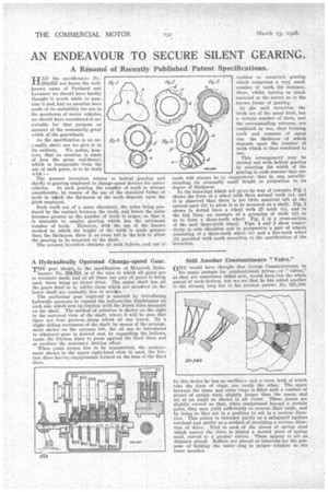
A Hydraulically Operated. Change-speed Gear.
Page 84
If you've noticed an error in this article please click here to report it so we can fix it.
THE gear shown, in the specification of Heinrich Bolts hauser,' No. 234,926, is of the type' in which all gears are in constant mesh, and at all times one pair of gears is being used, there being no directdrive. The upper shaft has all the gears fixed 'to it, whilst .those which are "tweeted on the
lower shaft are normally free to revoke. * The particular gear required is selected by introducing hydraulic pressure to expand the bellows-like diaphragms on each side which sets up friction with.the keyed discs mounted on the shaft. The method of selection is shown on the right. in the sectional view of the shaft, where it will be seen that there are four grooves,along which oil can travel. By a slight sliding movement of the shaft, by met= of the arrangement shown on the extreme left, the oil can be introduced to whatever gear is desired and, by expanding the bellows, cause the friction discs to press against the fixed discs and so produce the necessary driving effect.
• When great torque has to be transmitted, the arrangement shown in the tipper right-hand .vie* is used, the friction discs having engagements formed on the boss of the fixed discs.
Still Another Constantinesco "Valve."
ONE would have thought that George Constantinesco, in _ his many patents for unidirectional drives—or " valves,'.' as they are sometimes called now, would have run the whole gamut of such devices, but we see that he has added another to the already long list in his present patent, No. 281,380.
this device he has an oscillator and a rotor, both of which take the form of rings, one inside the other. The space between the inner and outer rings is filled with a number of pieces of spring steel, slightly longer than the space, and set at an angle as shown in all views. These pieces are slightly curved sothat, when compressed beyond a certain point, they may yield sufficiently to reverse their angle, and by doing so they are in a position to act in a reverse direction.. This action is intended -partly as a safeguard against overload and partly as a method of providing a reverse direction of drive. Next to each of the pieces of spring steel which convey the drive is placed a second piece of spring steel, curved to a greater extent. These appear to net as ,. distance piece. Rollers are placed at intervals for the purpesee of' holding • the 'outer: ring in proper • relation to the inner member.