


CONTINENTAL DESIGNS OF TRACTOR-LORRIES.
Page 32
If you've noticed an error in this article please click here to report it so we can fix it.
_ A Resume of Recently Published Patents.
SCOME INDICATION as to the lines which are being fob lowed by Continental makers of six-wheeled vehicles cannot fail to be of interest to all sections of the British commercial motor industry, whether they are concerned with the manufacture, sale or use of such vehicles. It is in that belief, at least, that we venture to give prominence this week to a couple of inventions which have just been registered in our British Patent Office by German and French engineers respectively.
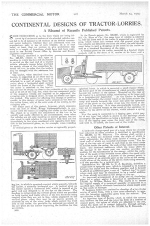
The former, described in specification No. 184,457, relates to that type of machine in which the fore end of a trailer is carried on the rear end of a tractor vehicle, adequate means lring pnovided for speedy release of the connection between the two, in order that the trailers may be changed withthe,minimum loss of time.
The trailer, when detached from the tractor, is supported at-its front-end on a pair of wheels on' an axle which is attached to a pair Of arms, • these-may swing about a horizontal shaft seciired below the frarne Of he trailer: . When the latter is attached to the tractor, the axle can be swung up close to the underside of the vehicle and so be out of the way, but when the two component part of the complete vehicle are required to be separated, the swinging axle is dropped down, so that its wheels rest upon the ground. The means. for effecting this 'change of position consist, in this deign; of _screw 'jacks secured at the,base of the trailer frame, and,' at the outer ends of the screws, to the
swinging axle. . ; • •
The major part of this patent., however,, which .ematiates from the firm. Of -Fried. Kink, Aktiengesellschaft, is concerned with the-means of 'coupling the trailer to the tractor.' The object is to enable the attachment of the two to be quickly and easily. effected in all circumstances, even when the vehicles are not only standing on uneven ground, but are also stood in such relation to one another that they are not immediately in line when considered with regard to their location in the horizontal plane, as, for example, when rounding a curve.
A vertical pivot on the tractor carries an upwardly project mg jaw, in which is mounted a socket which presents, tewards the trailer, a normally horizontal eye. A vertical pivot on the trailer carries a horizontal bolt., which is tapered at its outer end and designed to fit the eye on the tractor. The freedom to swing about the vertical pivots which are provided on both tractor and trailer allows of the two machines being coupled when they arc not in line, whilst alignment in the vertical plane, when they may be on uneven ground, is attained by use of the screw jacks which control the front axle of the trailer, the provision for universal movement of the eye piece on the tractor improving the facilities for this connection.
B44 In the French patent, No. 186,907, which is registered by Ste. Ch. Blum et Cie., the same type of vehicle is referred tO, but the front end of the trailer is supported on a vertical prop, which comes into contact with the ground when the two vehicles are detached one from the other, the said detachment being in part dropping of the front of the trailer as well as a rearward movement of the same.
. A vertical pivot on the trailer, mounted in a bracket which projects well to the front of it, carries at its lower end a
spherical block, in which is mounted a small runner wheel, the lower part of the circumference' of which projects slightly .beyond the surface of the sphere. Mounted on the rear of the tractde is a miniature ramp,terminating at its' inner end
in a hemispherical .depression. As the tractor is backed towards the trailer, the runner wheel on the latter mounts the t-ainp and travels towards the inner end until the spherical part of the pivot on the trailer drop's into the •recess at the inner end of the ramp. It is there automatically locked, and may not be released except,as Oa 'result Of the operation of a lever, by the driver of the tractor, which releases a spring catch.
Now the ramp is connected to a tipping gear, which may be of any type, but which is shown in the drawings which accompany the specification as being a hydraulic one. Operation of the tipping gear raises the inner end of the ramp, and with it, of course, the front endof the trailer.
Other Patents of Interest.
A hydraulic change-speed gear Of a type which has already had reference in these columns is described in specification No. 192,244, by W. Wharton. The driving shaft carries a rotor, on which are mounted vanes, the angle of which is easily adjustable; the driven shaft carries a casing, on the inner wall of which are mounted stationary vanes. The design of the two sets of vanes is such that as the rotor tends to revolve inside the casing, the ends of the vanes very nearly touch. The frictional resistance which the water offersto the passage of the vanes past one another provides the medium for the transmission of the energy, whilst the variation of the angle of the movable vanes affects the speed ratio of the rotor and casing. A feature of the present patent is the provision of an eincyclic gear in the cover of the casing, which allows of the motion of the driven shaft being reversed, and also provides for a neutral gear.
Specification NO. 192,166, by G. J. Racicham, describes a • simple form of epicyclic gear, which is intended to be located between the clutch and the ordinary gearbox, and is devised to afford an additional gear, a sort of indirect top," in cases where such gear may ho considered to be a useful addition to those already provided in the design of. the car. An improved arrangement of oil pump and oil circulating pipes for a rotary engine is described in specification No. 170,828, by William Motors Inc. The object is to ensure the regular supply of a measured quantity of lubricant to a specified spot, and to eliminate inaccuracies which might arise as the result of leakages. F. Laguesse makes the combustion chamber of a two-strolte engine of -spiral form, with a view more effectively to separate the incoming comhutible gases from the exhaust.. The specification is No. 178,818. An ingenious type of flexible wheel, in which the connection between the 'hub and rim takes the form of a number of conical parts, the apices of which are attached to the rim, whilst the bases are in contact indirectly, through springs,. with the hub, is described in No. 187,626, by E. Rartiondo.