


OVERHAULING• THE F.W.D.
Page 23
Page 24
Page 25
Page 26
If you've noticed an error in this article please click here to report it so we can fix it.
No. 23.—The F.W.D. Model B. The Three Types of Chassis. Dismantling for Overhaul. Dealing with the Units. What Requires Replacing, and Why. Points on Reassembling.
IN DEALING With the overhaul of the F.W.D. chassis, it must be remembered that there are actually three types in use in this country. There is the genuine commercial model produced by the makers, the F.W.D. Auto Co., of U.S.A., Canada and England, who are known in this country as the Four Wheel Drive Lorry Co., Ltd., 44-46, Kingsway, London, W.C. 2, with a spares and service department at Slough, Bucks. The second model is the American war chassis, which was made by outside concerns under the pressure of war requirements and embodied certain component changes from the standard type. The third model is the British, which was built by the Ministry of Munitions towards the close of hostilities. This deviates even farther from the genuine model and embodies parts which are' not interchangeable with those on the original type.
Spare parts for all F.W.D. machines can be obtained from the British builders, but, in any case, chassis and engine numbers should be given, as the carrying of the American nameplate on the radiator and dashboard does not necessarily signify that the lorry is a product of the F.W.D. plant. It is also desirable to state if the chassis is British or American.
So far as this article is concerned, we deal only with the genuine model, but Most of the remarks and methods of procedure can also be applied to the other two chassis.
Dismantling for Overhaul.
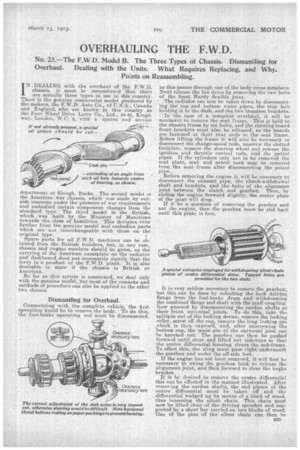
Commencing with the complete vehicle, the first operation would be to remove the body. To do this, the foot-brake operating rod must be disconnected, as this passes through one of the body cross-members. Next release the fan drive by removing the two bolts of the front Hardy flexible joint.
The radiafor can now be -taken down by disconnecting the top and bottom water pipes, the stay bolt holding it to the dash, and the two trunnion brackets. .` In the case of a complete overhaul, it will be necessary to remove the seat frame. This is held to the chassis frame by six bolts, and the running board front brackets must also be released, as the boards are fastened at their rear ends to the seat frame. Before lifting the frame it will also be necessary to disconnect the change-speed rods, unscrew the slotted footplate, remove the steering wheel and release the ignition and throttle control rods, and the petrol pipes. If the cylinders only are to be removed the seat plate, seat and petrol tank may be removed from the seat frame after disconnecting the petrol pipe.,
Before removing the engine it will be necessary to disconnect the exhaust pipe, the clutch-withdrawal shaft and braekets, and the bolts of the alignment joint between the clutch and gearbox. Then, by sliding the engine forward slightly, the centre plate of the joint will drop.
If it be a question of removing the gearbox and not the engine, then the gearbox must be slid back until this plate is free.
It is very seldom necessary to remove the gearbox, but this can be done by unbolting the back driving flange from the foot-brake drum and withdrawing the combined flange and shaft with the muff coupling. Now proceed by disconnecting the cardan shafts at their front universal joints. To do this, take the splitpin out of the locking device, remove the locking roller, screw off the cap, remove the long locking pin which is then exposed, and, after unscrewing the bottom cap, the main pin of. the universal joint can be knocked out. The gearbox can then be pushed forward until clear and lifted out sideways so that the centre differential housing clears the sub-frame. To effect this, the sling must pass right underneath the gearbox and under the off-side feet.
If the engine has not been removed, it will first be necessary to swing the gearbox back to release the alignment joint, and then forward to clear the brake bracket.
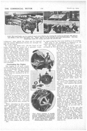
If it be desired to remove the e,entre differential this can be effected in the manner illustrated. After removing the cardan shafts, the end plates of the centre differential must be taken off and the differential wedged up by means of a block of wood, thus loosening the silent chain. This chain must now be lifted clear of the driving sprocket and supported by a short bar carried on two blocks of wood. One of the pins of the silent chain can then be
withdrawn, after, which the chain and the centre differential drawn side of the casing.
To remove the front axle, lift frame, preferably by means of a remove the front shackle bolts, front spring rear bracket bolts, steering connecting rod and the torsion rod hanger bolt A similar procedure can be followed with the rear axle, after disconnecting the hand.brake rod at the front end, when the axle can be wheeled out. It will only be necessary now to withdraw the brake drum and bearings.
Overhauling the Engine.
The engine is of Such simple construction, that it is unnecessary for us to describe how it may be dismantled. We would merely draw attention to the chief points which must be attended to in repairing it..
Perhaps of greatest importance is an improvement which can be
,effectedtto the crankshaft. This is provided with oil holes both in the main journals and in the bigend journals. A groove should be cut from each oil hole extending along the 'journal for about one inch. Great care must be taken that these grooves are properly arranged. Where they take up the oil on the main journals they must incline towards the direction of rotation at an angle of between 20 and 30 degrees from the longitudinal ; on the big-end jourmals they must incline away from the direction of rotation, as, in this
case, they deliver oil. In some cases the grooves may already 'be cut.
While attendingto this matter make certain that all the oil leads are thoroughly cleaned out ; paraffin should he forced through them under pressure. There is a chamfer on the lower ring groove of each piston ; this has a small hole connecting with -the gudgeon
pin bearing. The chamfer and hole must be kept free of carbon. Also see that the oil pump gauze is perfectly clean. To obtain access to this remove the oil pump
n36 by unscrewing the four -nuts holding it in position End play in the crankshaft -is adjusted at the centre bearing and must not exceed .010 in.
On the main bearings the brasses must be arranged so that the holes in them correspond with those in the crankcase, otherwise the oil-ways will be blocked.
If the timing gears mesh too deeply liners may 'be plazed under the main bearing ; or, if thought advisable, new bearings should be inserted. There a-re two cam'hafts, and at the back of the timing case will be found two setscrews screwed into the to of the crankcase and provided with lock nuts. To take up end play on either camshaft its respective setscrew must be screwed farther into the crankcase, after loosening the
leek-nut. Each setscrew is bevel pointed and presses against a bevelled collar. on the camshaft bush, so. that, as it is forced against the bush, it drives it in a longitudinal direction. After the end play has been taken up the setscrew lock-nut must again be tightened.
It is always advisable to renew the rollers and roller pins on the tappets. Also examine the guides for wear.
The oil pump is of the gear type, and although it has a very long life it is advisable to see that the 'pinions are not loose in their hearings; also see that the Pinion end faces are not Worn; otherwise oil will escape at the clearance between pinions and casing.
There is n felt washer on the pump drive spindle between the halves of the crankcase ; this washer mast be in -good condition. New felt washers should also be fitted at each end of the crankshaft in order to prevent less of lubricating oil.
The clutch is of the wet disc type, consisting of 12 phosphor. bronze and 11 steel discs alternately connected to the clutch case and the clutch centre. These plates are normally held in contact by a stout coil spring which should be checked as regards free length and should not be less than 4 ins. By removing the bolts in the clutch casing flange the centres come out with the plates_ The plates are locked in position 15y a spring ring which can be levered off by means of a screwdriver.
The pla,tes wear chiefly On the eastellatione, inner and outer ; the clutch core ca.stellations are about ele in thick, and if grooves are worn in them the plates will bind, with the result that the clutch cannot be released. The core and the castellations on the casings are of pressed steel, spot welded to the centre and the easing respectively, but the complete parts must he renewed if wear occurs.
Part sectional view of steering gear, showing reversible sleeve, which is both screwed and splined right. through; the double -thrust bearings a n d, above them, a portion of the thrust-adjusting Each clutch plate is provided with eight small ;steel springs, and these must all be truly circumferential, otherwise they will break off. If broken they must be renewed, or, if loose, the rivets must be tightened up. If the plates themselves are badly warn, these must also be replaced, or they may,cause trouble.
Dealing with the Gearbox.
To dismantle this, first remove the lid and then take out the six setscrews holding the front main drive housing, withdrawing the latter. Do the same with the housing at the rear end of the transmission shaft., and remove the chain pinion by using a special extractor' as shown In one of our illustrations. Remove the centre housing of the transmission shaft with its ball race, tip up the front end of the shaft and lift right, out.
We have assumed that the silent chain has already been removed as previously described.
If the countershaft bearings have to be removed the selector forks must be extracted by removing the split-pinned collars outside the gearbox, driving out the taper pins from the selector forks and then the selector fork shafts. The forks can then be lifted out. The countershaft can very easily be removed by withdrawing its bearing "housings. The selector gear is novel and very effective. A locking bar with a small movement is provided with two bevelended plungers, either one or other of which rests in a countersunk hole in a sector on one of the two selector forks ; the plunger down depends upon the fork • moved. • The arrangement is such that in no case could two forks be operated at the same time. There is also a spring locking ball for each selector fork. This bail springs into one of the three recesses which serve to indicate the correct positions for neutral or engagement of tkie sliding dog.
After a considerable time the fork recesses wear so that they are joined up by grooves. The forks should then be replaced. The locking plungers on the locking bar may require renewing ; in any case they should be carefully adjusted. The selector forks are provided with hardened steel studs working in hardened steel slippers. Both studs and slippers may have to be replace!i if they show much wear.
Gear changing is effected by dogs, and these maybe worn or chipped through bad driving, or by reason of a sticky clutch, in which case they may require renewing. When rebuilding the chassis, care must be taken to adjust the change-speed control .rods, so that the dogs Work freely and enable the spring balls to seat properly in the fork recesses. .
Examine the foot brake for the condition of the
Ferodo lining on the band ; if worn, renew. It must be remembered that there is a left-hand thread on the washer retainer. Renew the inner and outer felt washers.
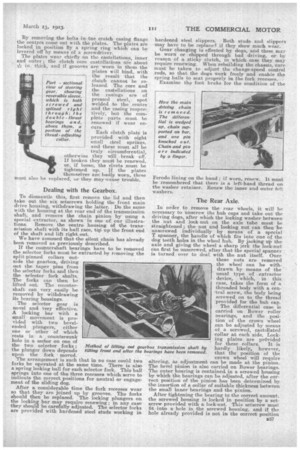
The Rear Axle.
In order to remove the rear wheel, it will be necessary to unscrew the hub caps and take out the driving dogs, after which the locking washer between the nut and lock-nut on the axle tube must be straightened ; the nut and locking nut can then be unscrewed individually by means of a special T spanner, the handle of which fits into one of the dog teeth holes in the wheel hub. By jacking up the axle and giving the wheel a sharp jerk the lock-nut can first be unscrewed, after that the special spanner is turned over to deal with the nut itself. Once these nuts are removed the wheel can be withdrawn by means of the usual type of extractor device, which, in this case, takes the form of a threaded body with a cenetral screw, the body being screwed on to the thread provided for the hub cap.
The differential case is carried on Bower roller oearings, and the posit-ion of the crown wheel can be adjusted by means of a screwed, castellated collar at each side. Locking plates are priivided for these collars. It is hardly likely, however, that the position of the
crown svheel will require -altering, as adjustment can be made, at the pinion_ The bevel pinion is also carried on Bower bearings. The outer bearing is contained in a screwed housing by which the bearings can be adjusted, after the correct powtion of the pinion has been determined by the insertion of a collar of suitable thickness between the small inner bearings and the pinion.
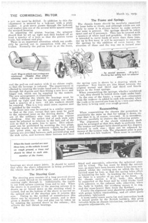
After tightening the bearing to the correct amount, the screwed housing is locked in position by a setscrew provided with a lock-nut.. This setscrew must fit into a hole in the screwed housing, and if the hole already provided is not in the correct position a new one must be drilled. In addition to this the adjustment is secured by a lock-nut with a plate washer. A grub screw passes through the lock-nut and washer into one of the several holes spaced round the screwed housing. . In adjusting the pinion bearing, the setscrew should first be set up tight and, then backed off at least a quarter of a turn so that the pinion turns freely, but without end play. There is an important alteration which can profitably be carried out in connection with the rear brakes. Normally the pull-on lever is at the front,
end the pull-on rod makes with it an obtuse angle, so that the leverage is reduced. The improvement is effected by rotating the brake band and its anchorage. through 180 degrees and then fitting a new lever and longer rod, which can be suppliedby the makers. . The new arrangement. is illustrated.
• After refitting the wheels the bearings must be pulled up tight and then the adjuSting nut taken back a quarter of a turn. All felt washers should be renewed. This is 'a very small extra expense and is justified by the results. The front axle may be treated in a similar manner to that at the rear, except that care must be paid to the universal joint on the driving shafts. These are of the ordinary star type and may require rebushing. Also the socket end of each stub axle must be adjusted in relation to the ball end of the axle so that it is quite free to move. This adjustment can be performed by screwing the two plugs, for what would, in thei ordinary vehicle, be the stub axle pivot pins, up or down. Hardened thrust buttons are provided between each screwed plug and the stub axles, and between these buttons and their hausings are stout paper joints. -It should be noted that while the above adjustment is being performed the wheels must be jacked up.
The Steering Gear.
The -steering gear consists Of a long screwed sleeve with a quick thread on its outside, and a slow thread running right through it. Additionally, the inside is cut with splines running from end to end. When the sleeve is in position in the steering column it is drawn up or forced down as the steering wheel is turned,and as the bottom of the sleeve is Carried on the splined end of the steering arm it rotates this arm. Owing to the method of manufacture -this sleeve can be reversed if wear occurs, and is thus given a double life. Any end play can be taken up byrotating the •screwed sleeve in the column ; this atljuss's the ball thrust bearings.
a38
The Frame and Springs.
The chassis frame should be carefully examined for loose bolts or rivets, and although cracks are not likely to occur it is always better to make certain that none is present. The springs should be taken apart and set if necessary. They can be treated with a mixture of white lead and graphite. lithe vehicle is intended to carry loads of more than three tons, say up to five tons, it will be necessary to reinforce the springs by the addition of extra leaves ; the situation of these and the way one i.s turned over the spring eyes is shown by a drawing which we reproduce. New leaves are also fitted betweenthe original second and third and third and fiiiirth leaves in the front springs. When reassembling the springs, whether reinforced or not, they should be bolted down tight under load.
In the case of the frame, a truss rod--obtainable from the makers—is added to each side-member when the leads to he carried are from :31 to 4 tons and where the lorry is being used over roughground.
Reassembling.
When reassembling the chassis the procedure is practically the same as that for taking it down,. except that it is, of course, reversed. It is necessary, however, carefully to observe the following points. The alignment of the clutch withdrawal shaft must be arranged so that this shaft is perfectly free. The torsion rod hanger bolts should point five degrees forward in each ease; these can be adjusted by means of the torsion rods. The alignment joint is provided with two feltwashers. These must be carefully
fitted and concentric, otherwise the spherical plate will be tilted. The fan must be fitted the correct way, as cases have been known where it has been.misplaced, whilst the rocking arm on which the fan is carried must be free, so that the spring takes effect in tensioning the belt. In tracking the front wheels. set these in a quarter of an inch at. the front. If the chassis carries a W.D. body, this should be supported at the front end by wood blocks lined with asbestos at the exhaust side, otherwise, when the body is loaded, the overhang causes it to sag, and the cross bearer then fouls the flywheel.
Finally the alignment joint should be packed tightly with grease before reassembling, and all other parts adequately lubricated. A most useful spare parts list, and instruction book is issued gratis by the British blinders, this gives valuable hints on chassis hibrication, carburetter and magneto adjustments, etc.