


• For DRIVERS, MECHANICS & FOREMEN.
Page 21
If you've noticed an error in this article please click here to report it so we can fix it.
A PRIZE OF TEN SIIILLINGS is awarded each week to the sender of the best letter which we publish on this page ; all °ther3 are paid for at the rate of a penny a line, with an allowance for photographs. All notes are edited before being published. Alentian your employer's name, in confidence, as evidence of good faith. Address, D„ M. and F., "The Commercial Motor," 7-35, Rosebery Avenue, London, E.G. -I.
Lamps Alight.
On Saturday, March 15th, light your .Lamps art 6.32 in London, 7.15 hi Edinburgh, 6.38 in Newcastle, 6.44 in Liverpool, 6.39 in Birmingham, 6.42 in Bristol, and 7.26 in Dublin.
A Universal Wheel Puller:
The sender of the following communication has been awarded the Ws. prize this week.
[1952] " H.J.0." (Chismiek) writes :—" The, accompanying sketch (which ÷we have had 'redrawn—En.) illustrates a useful wheel drawer, which is adjustable for various sizes and types of wheels. It may be used for road wheels, and also for spur wheels on gearbox shafts, and similar parts. It is designed so that it can be easily made in the shop with the minimum of tooling, and from odd scrap pieces that will be found in almost every works? no matter how small.
"A, the crossbar, is cut from a piece of mild steel or wrought iron of square section, 1 in. by 1i in. by 9 ins. long. Two slots must be cut in it as shown in the plan view, Fig. 2, and a hole in the centre drilled and tapped in. Whitworth. Lay it, then, on its side. and drill right through four holes for in. bolts or pins. Actual dimensions for the position of these holes are not given. The mechanic will be able to mark it out for himself in accordance with the size of work with which he is usually occupied. The parts
B are shaped from pieces of 11 in. by in. bar, again either of wrought iron or mild steel. They should be forged to the shape shown in the sketch, one end of each being bent over to form a lip. These parts (B) must be made to fit nicely into the jaws of A, and four or five in. holes should then be drilled in each as shown, to accommodate the bolt or pin which passes through A and B together. C is cut from a piece of 111 in. by in. or 1 in. by in. bar ; the hole in the centre is a clearance hole for in. screw. The slots at the end are in. wide and in. deep. The screw is merely a length of screwed in. steel, with a square or hexagon at one end to accommodate a span7
ner, and fitted at the other end with a cap, the surface of which should be chequered so that it will not slip off the end of the shaft or axle from which the wheel is being withdrawn.
"A glance at the two arrangement drawings will show the limits within which this 'tool may be used, depending upon the dimensions adopted by the maker. The part C, it will be noted, is only needed in. the case -of small wheels when. there might he a tendency for the arras (B) to slip out of place. With. the plate (C) pushed down into position with the slots which are cut in it registering with the inside tapered portion of the arms, and a I in. nithrun down so as to hold it in that. position, there will then be no fear of this slipping taking place. "It is a good tip, when withdrawing road wheels,
to and the arms of the puller between the spokes, and lay shortalengths of bar on the insi4ile of the spokes, with which bar thei ends of the arms can engage."
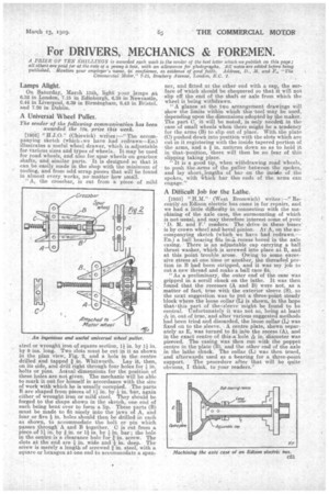
A Difficult Job for the Lathe.
[1953] " H.M." (West Bromwich) writes :-.." Recently an Edison electric bus came in for repairs, and we had a little difficulty in connection with the machining of the axle case, the surmounting of which is not usual, and may therefore interest some of your 'D. M. and F.' readers. The drive in these buses' . is by crown wheel and bevel pinion. At A, on the accompanying sketch (which we have had redrawn.— Fm) a ball bearing fits in■-a, recess bored in the axle casing. There is an adjustable cap carrying a ball thrust washer, which is screwed into place at 13, and at this point trouble arose. Owing to some excessive stress at one time or another, the threaded portion in B had been stripped, and it was my job to cut a new thread and make a. ball race fit, "As a preliminary, the enter end of the case was gripped in a. scroll chuck on the lathe. It was then found that the recesses (A and B) were not, as a matter of fact, true with the exterior sleeve (S), so the next suggestion was to put a three-point steady block where the loose collar (L) is shown, in the hope that-,this part of the s sleeve might be found to he central. Unfortunately it was not so, being at least
in. out of true:and after various suggested methods had been tried and discarded, the loose collar (L) was fixed on to the sleeve. A centre plate, shown separately as E, was turned to fit into the recess (A), and in the exact centre of this .a hole in. diameter was pierced. The casing was then run with the poppet centre in the plate (13), and the other end of the axle in the lathe chuck. The collar (L) was then trued, and afterwards used as a bearing for a three-point support. The procedure after that will be quite obvious, I think, to your readers."