


A Pneumatic Suspension Unit
Page 58
If you've noticed an error in this article please click here to report it so we can fix it.
AIR is used as the resilient medium in a suspension unit shown in patent No. 670,044 1y R. Clerk, Tadcaster Court, Clarence Street, Richmond, Surrey. The chief point of
the scheme is the means for giving an increasing rate of compression higher than that provided naturally by the compression of the air.
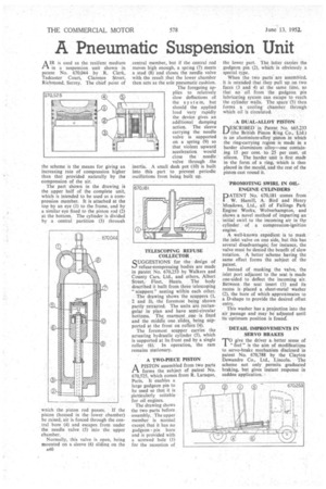
The part shown in the drawing is the upper half of the complete unit, which is intended to be used as a corn-pression member. It is attached at the top by an eye (1) to the frame, and by a similar eye fixed to the piston rod (2) at the bottom. The cylinder is divided by a central partition (3) through
wnich the piston rod passes. If the piston (housed in the lower chamber) be raised, air is forced through the cen_ tral bore (4) and escapes from under the needle valve (5) into the upper chamber.
Normally, this valve is open, being mounted on a sleeve (6) sliding on the A40
central member, but if the central rod moves high enough, a spring (7) meets a .stud (8) and closes the needle valve with the result that the lower chamber then acts as the sole Pneumatic cushion.
The foregoing applies to relatively slow deflections of the system, but should the applied load vary rapidly the device gives an additional damping action. The sleeve carrying the needle valve is supported on a spring (9) so that violent upward acceleration would close the needle valve through .the inertia. A small dash pot (10) is built into this part to prevent periodic oscillations from being built up.
TELESCOPING REFUSE COLLECTOR
SSUGGEST S for The design of refuse-compressing bodies are made in patent No. 670,253 by Walkers and County Cars, Ltd., and others, Albert Street, Fleet, Hants. The body described it built from three telescoping " scuppers" nesting within each other. . The drawing 'shows the scuppers (I, 2 and 3), the foremost being shown partly retracted. The units are rectangular in plan and have semi-circular bottoms. The rearmost one is fixed and the middle one slides, being supported at the front on rollers" (4).
The foremost scupper carries the actuating hydraulic cylinder (5), which is supported at its front end by a single roller (6).' In operation, the ram remains stationary.
. A TWO-PIECE PISTON
APISTON assembled from two parts forms the subject of patent No. 670,525, which Comes from R. Laraque, Paris. It enables a large gudgeon pin to be used so that it is Particularly suitable for oil engines.
The drawing shows the two parts before assembly. The upper member is normal except that it has no gudgeon-pin bore and is provided with a screwed hole (1) for the reception of the lower part. The latter carries the gudgeon pin (2), which is obviously a special type.
When the two parts are assembled, it is intended that they pull up on two faces (3 and 4) at the same time, so that no oil from the gudgeon pin lubricating system can escape to reach the cylinder walls. The space (5) then forms a cooling chamber, through which oil is circulated.
A DUAL-ALLOY PISTON
DESCRIBED. in Patent No. 665.233 (the British Piston Ring Co., Ltd.) is an aluminium-alloy piston in which the ring-carrying region is made in a harder aluminium alloy—one containing 15 per cent. to 25 per cent. of silicon. The harder unit is first madt in the form of a ring, which is then placed in the mould, and the rest of the piston cast round it.
PROMOTING SWIRL IN OILENGINE CYLINDERS PATENT No. 670,181 domes from W. Hamill, A: Bird and Henry Meadows, Ltd., all of Fallings Park Engine' Works, Wolverhampton, and shows a novel method of imparting an initial swirl. to the incoming air in tiv cylinder, of a compression-ignition engine.
A well-known expedient is. to mask the inlet, valve on one side, but this has several disadvantages; for instance, the valve must be denied the benefit of slow rotation. A better scheme having the same effect forms the subject of the patent.
Instead of masking the valve, the inlet port adjacent to the seat is made one-sided to deflect the incoming air. Between the seat insert (I) and its recess is placed a sheet-metal washer (2), the bore of which approximates to a D-shape to provide the desired offset entry.
This washer has a projection into the air passage and may be adjusted until its optimum position is found:
DETAIL IMPROVEMENTS IN SERVO BRAKES
TOgive the driver a better sense of " feel " is the aim of modifications to servo-brake mechanism disclosed in patent No. 670,788 by the Clayton Dewandre Co., Ltd., Lincoln. The scheme not only permits graduated braking, but gives instant response in sudden application.