


CARBURETTERS AND BRAKES.
Page 34
If you've noticed an error in this article please click here to report it so we can fix it.
A Resume of Recently Published Patents.
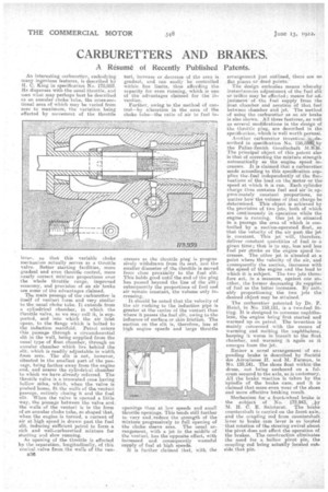
An interesting carburetter, embodying many ingenious features, is described by H. C. King in specification No. 1787959. He dispenses with the usual throttle, and uses what may perhaps best be described as an annular choke tube, the cross-sectional area of which may he varied from
• zero to maximum, the variation being effected by movement of the throttle lever, so that this variable choke mechanism actually serves as a throttle valve. Better starting facilities, more gradual and even throttle control, more nearly correct mixture proportions over the whole throttle range, improved economy, and provision of an air brake are some of the advantages claimed.
The main passage of the carburetter is itself of venturi form and very similar to the usual choke tube. It extends from a cylindrical chamber, in which the throttle valve, as we may calf it, is supported, and into which the air inlet opens, to the flange which is bolted to the induction manifold. Petrol enters this passage through a circumferential slit in the wall, being supplied from the usual type of float chamber, through an annular chamber which lies behind the alit, which is readily Adjustable in width from zero. The slit is not, however, situated in the smallest part of the passage, being farther away from the engine end, and nearer the cylindrical chamber to which we have already referred. The throttle valve is a truncated cone having hollow sides, which, when the valve is pushed home, fit the walls of the venturi passage, entirely closing it and the fuel slit. When the valve is opened a little way, the passage between the valve and the walls of the venturi is in the form of an annular choke tube, so shaped that, when the engine is turned, a current of air at high speed is drawn past the fuel slit, inducing sufficient petrol to form a rich and well-carburetted mixture for starting 'and slow running.
As opening of the throttle is effected by theseparation, longitudinally, Of this conical -valve from the walls of the yen
3336
turi, increase or decrease of the area is gradual, and can easily be controlled within, fine limits, thus affording the capacity for even running, which is one of the advantages claimed for the invention.
Further, owing to the method of control—by alteration in the area of the choke tube—the ratio of air to fuel -in
• creases as the throttle plug is progres sively withdrawn from its seat, and the smaller diameter of the throttle is moved from close proximity to the fuel slit. This holds good until the end of the plug has passed beyond the. line of the slit; subsequently the proportions of fuel and air remain constant-, the volume only increasing..
• It shoUld be noted that the velocity of the air rushing to the induction pipe is greater at the centre of the venturi than where it passes the fuel slit, owing to the influence of surface or skin friction. The suction on the slit is, therefore, less at high engine speeds arid large throttle openings than at low speeds and sins 1 throttle openings. This tends still further to vary and:reduce the strength ofthe Mixture progressively to full opening of the chokesleeve area. The usual arrangement, with a jet in the middle of the venturi, has the opposite effect, with increased and consequently Wastefol supply of fuel at high speeds. . is further claimed that with the arrangement just outlined, there are no flat place S or dead points.
The design embodies means whereby instantaneous adjustment of the fuel alit or orifice may be effected; means for adjustment of the fuel supply from the neat, chamber and aeration of that fuel between chamber and jet. The method of usiliF the carburetter as an air brake is also /own. All these features, as well ra several modifications in the design of the throttle plug, are described in the specification, which is well worth perusal.
Another carburetter invention
scribed in specification No. 158,53-Why the PalLas•Zenith Gesellschaft 1d./1.1-1. The principal object of this patent also is that of correcting the mixture strength automatically as the engine speed increases. It is claimed that a carburetter made according to this specification supplies the fuel independently of the fluctuations of the load on the motor or the speed at which it is run. Each cylinder charge thus contains fuel and air in approximately constant prOportions, iso triatt•er how-the volume of that charge be determined. This object is achieved by the provision of two jets, both of which are continuously in operation while the engine is running. One jet is situated in a passage the area of which is controlled by a suction-operated float, so that the velocity of the air past the jet is constant. This jet will, therefore, deliver constant quantities of fuel in a given time; that is to say, less and less fuel per Stroke as the engine speed increases. The other jet is situated at a point where the velocity of the air, slid consequently the suction, increases with the speed of the engine and the load to which it is subject. The two jets therefore act, in a measure, against one another, the farmer decreasing its supplies of fuel as the latter increases. By suitably proportioning the two jets the desired object may he attained.
. The carburetter patented by Dr. F. Heinl, in No. 159,181, is a two-fuel fittiug. ft is designed to consume naphthalene, the engine being first started and warmed up on petrol. The invention is mainly concerned with the means of warming and meltiog the naphthalene, keeping it warm in transit to the float chamber, and warming it again as it emerges from the jet.
Rather a novel arrangement of expanding brake is described by Societe des Aeroplanes H. and M. Farman, in No. 159,141. The shoes float within the drum, nut being anchored on a. fulcrum secured to the axle, as is customary. AB the brake reaction is taken by the ispindle of the brake cam, and it is claimed that more even wear of the shoes and more effective braking result.
Mechanism for a front-wheel brake is' the a-object of No. 172,943, Aiy M. H. C. E. Sainturat. The brake countershaft is carried on the frontaxle,.
and the coupling rod from countershaft lever to brake cam lever is so located that rotation of the steering swivel about the pivotdoes not affect the operation of the brakes. The construction eliminates the need for a hollow pivot pin, the coupling rod being actually located outside that pin.