


Remote Control for Brake Adjusters
Page 32
If you've noticed an error in this article please click here to report it so we can fix it.
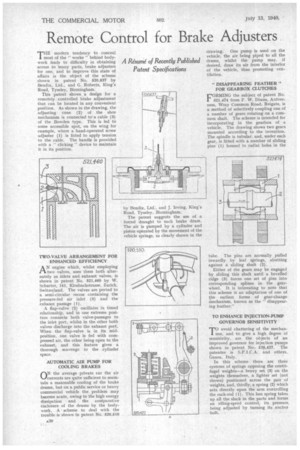
THE modern tendency to conceal most of the " works" behind bodywork leads to difficulty in obtaining access to nany parts, brake adjusters for one, and to improve this state of affairs is the object of the scheme shown in patent No. 520,637 by Bendix. Ltd., and G. Roberts, King's Road, Tyseley, Birmingham.
This patent shows a design for a remotely controlled brake adjustment that can be located in any convenient position. As shown in the drawing, the adjusting cone (2) of the shoe mechanism is connected to -a cable (3) of the Bowden type. This is led to some accessible spot, on the wing for example, where a hand-operated screw adjuster (1) is fitted to apply tension to the cable. The handle is provided with a " clicking " device to maintain it in its position.
AN engine which, whilst employing two valves, uses them both alternately as inlets and exhaust valves, is shown in patent No. 521,460 by W. Schurter, 141, Klosbachstrasse, Zurich, Switzerland. The valves are ported to a semi-circular recess containing the pressure-fed air inlet (3) and the exhaust passage (1).
A flap-valve (2) oscillates in timed relationship, and in one extreme position connects both valve-passages to the inlet port, whilst in the other both valves discharge into the exhaust port. When the flap-valve is in its midposition, one valve is fed with compressed air, the other being open to the exhaust, and this feature gives a thorough scavenge to the cylinder space.
AUTOMATIC AIR PUMP FOR COOLING BRAKES
ON the average private car the air currents are quite sufficient to maintain a reasonable cooling of the brake drums, but on a public service or heavy commercial vehicle the problem may become acute, owing to the high energy dissipation and the coniparative enclosure of the drums by the bodywork. A scheme to deal with the trouble-is shown in patent No. 520,610
by Bendix, Ltd., and J. Irving, King's Road, Tyseley, Birmingham.
The patent suggests the use of a • forced draught to each brake drum. The air is pumped by a cylinder and piston operated by the movement of the vehicle springs, as clearly shown in the drawing. One pump is used on the vehicle, the air being piped to all the drums, whilst the pump may, if desired, draw its air from the interior of the vehicle, thus promoting ventilation.
"DISAPPEARING FEATHER" FOR GEARBOX CLUTCHES
FORMING the subject of patent No. 521,474 from F. W. Dixon, Ardverness, Wray Common Road, Reigate, is a method of selectively coupling one of a number of gears rotating on a common shaft. The scheme is intended for incorporating in the gearbox of a vehicle. The drawing shows two gears mounted according to the invention. The spindle is tubular, and, under each gear, is fitted with a number of sliding pins (1) housed in radial holes in the
tube. The pins are normally pulled inwardly by leaf springs, abutting against a sliding shaft (2).
Either of the gears may be engaged by sliding this shaft until a bevelled ridge (3) forces one set of pins into corresponding splines in. the gearwheel. It is interesting to note that this scheme is an adaptation of one of the earliest forms of gear-change inechanism, known as the "disappearing feather."
TO ENHANCE INJECTION-PUMP GOVERNOR SENSITIVITY TO avoid chattering of the mechan
ism, and to give a high degree of sensitivity, are the objects of an improved governor for injection pumps shown in patent No.. 520,427. The patentee is S.P.I.C.A. and others,
Genoa. Italy. •
In this scheme there are three systems of springs opposing the centrifugal weights—a heavy set (3) on the weights themselves, a lighter set (not shown) positioned across the pair of weights, and, thirdly, a spring (2) which acts directly upon the arm controlling the rack-rod (I). This last spring takes up all the slack in the parts and forms an idling-speed control, its pressure, being adjusted by turning its anchor bolt.