


Two-stroke Engine Developments
Page 60
If you've noticed an error in this article please click here to report it so we can fix it.
A Résumé of Recently Published Patent Specifications
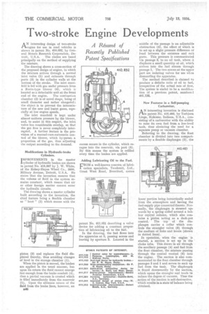
AN interesting design of two-stroke engine for use in road vehicles is shown in patent Pio. 410,802, by General Motors Research Corporation, De
troit, U.S.A. The claims are based principally on the method of supplying the mixture. • The drawing shows a cross-section of the proposed design of engine, in which the mixture arrives through a normal inlet valve (1) and exhausts through ports (3) in the cylinder walls at the bottom of the stroke. The inlet manifold is fed with gas under pressure from a Roots-type blower (4), which is located as a detachable unit at the front end of the engine. The combustion chamber (2) is of novel shape, being of small diameter and rather elongated; the object is to prevent the intermixture of the new and burnt gases, especially at low engine speeds.
The inlet manifold is kept under almost uniform pressure by the blower, and, to assist in this respect, the inlet valve has Considerable overlap, so that the gas flow is never completely interrupted. A further feature is the provision of a manual-cum-automatic control of the blower, which by=passes a proportion of the gas, thus adjusting the output according to the demand.
Modifications in Hydraulic-brake Cylinders.
IMPROVEMENTS in the master !cylinder of hydraulic brakes are shown in patent No. 410,367 by J. W. White, of the Kelsey-Hayes Wheel Co., 3600, Military Avenue, Detroit, U.S.A. He states that the invention ensures that the volume of fluid in the system remains constant, which means that air or other foreign matter cannot enter the hydraulic circuits.
The drawing shows a master cylinder built according to the invention, the chief feature being a flexible chamber or " boot " (2) which moves with the piston (3) and replaces the fluid displaced thereby, thus avoiding changes of level in the storage chamber (1).
When the piston is moved, the brakes are applied in the usual manner, but upon its return the fluid cannot emerge fast enough from the brake conduit (4), thus a partial vacuum is created which is filled immediately from the reservoir (1). Upon the ultimate return of the fluid from the brake lines, however, an
excess occurs in the cylinder, which escapes into the reservoir, via port (5). I3y this means the system is refilled every time the brakes are applied.
Adding Lubricating Oil to the Fuel.
FROM a well-known concern of lubrication specialists, Tecalemit, Ltd., Great West Road, Brentford, comes patent No. 411,051 describing a valve device for adding a constant proportion of lubricating oil to the fuel.
In the drawing, the fuel flows into the apparatus at 3, passing across and leaving by aperture 5. Located in the middle of the passage is an adjustable obstruction (4), the effect of which is to set up a slight pressure difference or head between the entrance and exit ports. This pressure is communicated via passage 2, to an oil tank, where it displaces a small quantity of oil, which arrives into the fuel stream through passage 1. The two screws at the upper part are isolating valves for use whmi dismantling the apparatus.
The method described is claimed to produce a definite ratio of oil to fuel, irrespective of the actual rate of flow. The system is stated to be a modification of a previous patent, numberel 401,126.
New Features in a Self-pumping Carburetter.
AN interesting invention is disclosed in patent No. 410,483, by Torbjorn Linga, Kokomo, Indiana, U.S.A., consisting of a carburetter with the ability to raise its own fuel from a low-level tank, thus obviating the need for a separate pump or vacuum chamber.
Referring to the drawing, the float chamber is divided into two compartments by a flexible diaphragm (2), the
lower portion being hermetically sealed from the atmosphere and having the fuel-supply pipe connected thereto. Normally, the diaphragm is stressed upwards by a spring coiled around a hollow central column, which also contains a piston acting as a dash-pot control. The ,top of the diaphragm carries a collar which controls the strangler valve (5) through the medium of links and levers (shown in dotted. lines).
In opera.tion, when the engine started, a suction is set up in the choke tube. This draws in air through the auxiliary passage (4) and fuel from the float chamber, the mixture passing through the central venturi (6) into the engine. The suction is also communicated to the float chamber through passages 3 and I and serves to suck up fuel from the tank. The diaphragm is flexed downwardly by the suction, which opens the strangler and tends to reduce the degree of vacuum. Thus the action of the suction is self-destructive, which results in a state of balance being obtained.