


Abridgments of Interesting Patent Specifications.
Page 18
If you've noticed an error in this article please click here to report it so we can fix it.
No. 13,101 : dated June roth, iy04.—F. N. Baker, of Messrs. Cammell, Laird and Co., Coventry.—This specification describes worm gearing so adjustable that backlash is reduced to a minimum. The thread of the worm instead of forming one solid spiral is split into two spirals (A and B), which after being threaded together are locked in abutment by rings
(C and D). The pitch of the abutting surfaces indicated by line (E) is greater than the pitch of the working surfaces (a and b). Consequently by causing one spiral to advance to the requisite extent relatively to the other, the width of the split thread is increased sufficiently to fill the space between two teeth of the wormwheel, wear being thereby fully compensated for.
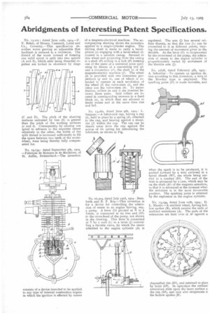
No. /9,134: dated September 5th, 1904. —Fabrique de Moteurs et de Machines, of St. Aubin, Switzerland.—The invention consists of a device intended to be applied to any type of internal combustion engine in which the ignition is effected by means
of a magneto-electrical machine. The accompany mg drawing shows the invention applied to a single-cylinder engine. The driving shaft is made to carry a bevel. pinion (a) engaging with a bevel-wheel (b) located in a suitable casing. Secured to this wheel and projecting from the casing is a shaft (b1) ending in a fork (b2) forming one of the parts of a universal joint operating by means of a connecting rod (d) and a connection (e1), the shaft (e) of the magneto-electric machine (f). The wheel (b) is provided with two concentric projections (g and h), one of which is intended to operate at each revolution of the wheel (b) the valve-stem (i), and the other one the valve-stem (k). To lessen friction, rollers (m and 1) are inserted between these parts. Said rollers are located in corresponding recesses in a fixed block (a), in which they are allowed to freely rotate and at the same time rise and fall.
No. 13,060, dated June yth, 1904: L. Samann.—A lubricator cup, having a cap (b), held in place by a spring (d), attached to the cap, and bearing against a shoulder (f) within the cup. The cap can be drawn away from the cup against the action of its spring for introducing the lubricant, as shown in Fig.
No. 16,303, dated July 23rd, 1904: Barn. forth and R. P. Roy.—This invention is for a device for controlling the admission of steam to an engine 'driving, say, a pump. A lever (0) pivoted at N to a frame, is connected at its free end (01) to the cross-head of the pump, not shown in the drawing. This lever is connected at N by a cord (L) to a lever (J1 controlling a throttle valve, by which the steam admitted to the engine cylinder (A) is regulated. The arm (J) has several orifices therein, so that the line (I-) can be connected to it at different points, varying the amount of movement given to the throttle. As the lever (0) is reciprocated by the cross-head of the pump, the admission of steam to the engine cylinder is proportionately varied by movement of the throttle arm (J).
No. 2,628, dated February 9th, 1905 A. Schoeller.—To operate an ignition device according to this invention, a wire of the Bowden type is employed. The sparking point (Si) is made movable, and
when the spark is to be produced, it is pushed forward by a wire enclosed in a spiral sheath (W1), the whole being carried in a conduit (R1). The end of the wire is advanced by a cam, which may be on the shaft (Al) of the magneto armature, so that it is advanced at the moment when the armature is in the most favourable position. The sparking point is returned by the explosion in the engine cylinder.
No. 13,199, dated June iith, 1904 : D. L. Master.—A resilient wheel, having hollow spokes (B), which receive the ends of resilient extensions (A). The ends of the extensions are bent over at Al against a channelled rim (D1), and retained in piaci by bolts (D2). In operation the resilient extensions slide upon the inner surface o: the rim (D1), and may also reciprocate ir the hollow spokes (B).