


The Rolls Omnibus.
Page 12
Page 13
If you've noticed an error in this article please click here to report it so we can fix it.
The latest production to come under our notice emanates from the well-known house in Conduit Street, and bears the impress of much thought in the devising of the splendid chassis we have just inspected. Considerable pains have been taken to secure ease of detachment, as well as of adjustment, of every working part, whilst at many points quite original features are introduced, all tending to make control purely mechanical. This is of importance when all sorts of drivers will have charge, and should more particularly appeal to large users. On the Rolls bus there is only a throttle lever, all else being engine-controlled.
Dealing first with the general features, we find the frame to be built of channel steel of deep section, with the usual cross members and corner stiffeners. The disposition of the various portions of the propelling mechanism is in accordance with what has been found desirable from previous experience with public service vehicles. The chassis was illustrated in our previous issue on page 339, but note should be made that the wheels there shown are only temporary, .dished wheels with twin tyres as to the rear being the standard.
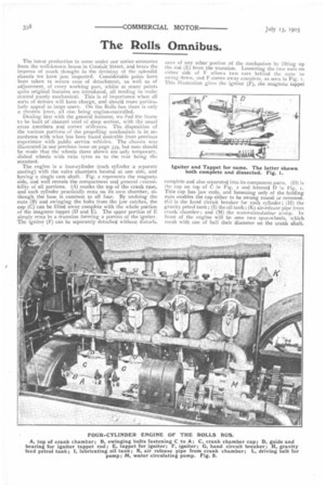
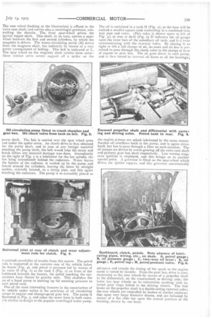
The engine is a four-cylinder (each cylinder a separate casting) with the valve chambers located at one side, and having a single cam shaft. Fig. 2 represents the magneto side, and well reveals the compactness and general ccessi bility of all portions. (A) marks the top of the crank case, and each cylinder practically rests on its own chamber, although the base is common to all four. By undoing the nuts (B) and swinging the bolts from the jaw catches, the cap (C) can be lifted away complete with the whole portion of the magneto tappet (D and E). The upper portion of E simply rests in a trunnion forming a portion of the igniter. The igniter (E) can be separately detached without disturb.
ance of any other portion of the mechanism by lifting up the rod (E) from the trunnion. Loosening the two nuts on either side of E allows Iwo ears behind the nuts to swing down, and E comes away complete, as seen in Fig. I. This illustration gives the igniter (F), the magneto tappet complete and also separated into its component parts. (D) is the cap on top of C in Fig, 2 and lettered Ei ;ri Fig. 1. This cap has jaw ends, and loosening only of the holding nuts enables the cap either to be swung round or removed (C) is the hand circuit breaker for each cylinder; (II) the gravity petrol tank ; (I) the oil tank ; (R) air-release pipe from crank chamber; and (M) the water-circulatingteimp. In front of the engine will be seen two spur-wheels, which mesh with one of half their diameter on the crank shaft.
The rear wheel (looking at the illustration) is affixed to the valve cam shaft, and carries also a centrifugal governor, controlling the throttle. The front spur-wheel drives the igniter tappet shaft. This shaft, in its turn, carries a spurwheel between the first and second cylinders, by which the magneto is driven. The water-circulating pump (M) drives from the magneto shaft, but indirectly by means of a very pretty arrangement of belting. This belt is indicated at L. The spur wheel on the magneto shaft carries three arms : three sitniiar arms secure support off a spider on the
pump shaft. The belt is carried over the spur wheel arms and under the spider arms. An elastic drive is thus obtained for the pump shaft, and in case of any foreign material reaching the pump teeth, the belt would take the strain and break before any material damage was done. Immediately on the right of Fig. 2 is a lubricator for the fan spindle, the fan lying immediately behind the radiators. Water leaves the bottom of the radiator, is sucked up by the pump and forced around the cylinders, leaving the latter by straight outlets, centrally located, to a rising pipe, and this again reaching the radiators. The pump is so accessibly placed as o preclude possibility of trouble from this source. The petrol .rink is supported at the extreme tear of the vehicle below he frame (Fig. 4), and petrol is pressure fed by means of he valve H (Fig. 6) to the tank I (Fig. 2) on iront of the lashboard beneath the bonnet, the petrol reaching the carairetters from thence by gravity only. This abolishes the Ise of a hand pump in starting up for securing pressure to nain petrol tank.
One of the most interesting features in the construction of he vehicle under notice is the provision of oil circulating ■ unips to engine and change-speed gear box. The pump is llustrated in Fig. 3, and takes the same form in both cases. t is similar in design to the popular centrifugal water pump. The oil is contained in a tank H (Fig. 2); at the base will be noticed a smaller square tank connecting to a combined twoway pipe and valve. This valve is shown apart to left of Fig. 3); at rear of dash (Fig. 6) D indicates the oil gauge upon the inner face of the subsidiary oil tank, and G a lever communicating with the two-way valve. By placing G to right or left a full charge of oil, no more and no less is permitted to pass through the check valve to the pumps at base of engine or gear box. The oil goes direct to each pump, and is then forced by internal oil ducts to all the bearings; the engine pistons are splash lubricated by the same means. Surplus oil overflows back to the pump, and is again circulated, but has to pass through a filter on each occasion. The oil pumps are driven by worm gearing off the valve cam shaft and primary gear box shaft respectively. Low tension magneto ignition is employed, and this brings us to another special point. A governor is fitted on the spur-wheel which drives the igniter tappets, and this governor automatically advances and retards the timing of the spark as the engine speed is varied by throttle. From the gear box, drive is communicated to the rear wheels by means of a propeller shaft to the differential, on the countershaft or driving axle; the latter has spur wheels on its extremities meshing with internal gear rings bolted to the driving wheels. The foot brake on the propeller shaft is a double-acting external yoke; th,c rear wheels are controlled by brakes of similar construction upon very large diameter drums, and are balanced by means of a flat slide bar upon the central portions of the framing, drawn by one lever.