


THORNYCROFT'S LATE iT RIGID SIX-WHEELER S HORTLY before the Commercial Motor
Page 54
Page 55
Page 56
Page 57
If you've noticed an error in this article please click here to report it so we can fix it.
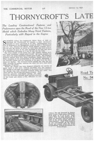
Show of 1929 we described the Thornycroft JC chassis, a rigid six-wheeler intended to carry pay-loads of 10 tons. Developments have been in progress at the Basingstoke works of John I. Thornycroft and Co., Ltd., Thornycroft House, Smith Square, London, S.W.1, and the new QC series, to which we refer here, has been evolved. The pay-load of each of the new machines is 12 tons and there is an additional allowance of 1 ton 10 cwt. for the body.
The three models of the series are :—QC, normal control, 14-ft. 6-in, mean wheelbase, chassis price £1,410. QC Long, normal control, 16-ft. 9-in, mean wheelbase, chassis price £1,450. QC Forward, forward control, 14-ft. 6-in, mean wheelbase, chassis price £1,450. With exception of the arrangement of the controls, disposition of the steering column and the mounting of the gear lever the three types are similar. The forward-control chassis has only one fuel tank, carrying 50 gallons, whereas the other two have dual tanks containing 79 gallons.
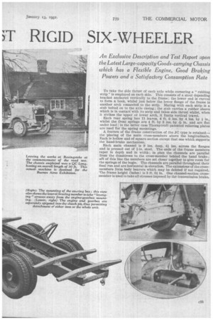
Whilst the chassis has been designed primarily for service on made roads it will carry reduced pay-loads over bad surfaces. The springs of the bogie are coupled to the axles without trunnions; the springs thus take whatever torsional loads may arise ; they cater also for the driving and torque stresses. Four Inverted, gaitered, semi-elliptic springs are used ; each pair is pivoted centrally upon brackets attached to the frame and allows a 6-in, difference in axle level.
To take the side thrust of each axle while cornering a "rubbing strip" is employed on each side. This consists of a stout depending bracket anchored vertically to the frame; the lower end is curved to form a hook, whilst just below the lower flange of the frame is another arch connected to the strip. Mating with each strip is a stub bolted on to the axle casing ; the stub carries a rubber sleeve which is in contact with its strip and takes side thrust whilst, when it strikes the upper or lower arch, it limits vertical travel. Each rear spring has 11 leaves, 4 ft. 6 ins. by 4 ins. by in., whilst the front springs are 4 ft. by 3 ins. by 176in. and are flat tinder load ; in the latter case Thornycroft patented relieving plates are used for the spring mountings.
A feature of the frame construction of the JC type is retained— the placing of the main cross-members above the longitudinals. Each is hollow and of square section except that one which supports the hand-brake mechanism.
Each main channel is 9 ins. deep, 4i ins, across the flanges and is pressed out of fin. steel. The ends of the frame members taper in depth and in width ; in plan the channels are parallel from the dumbirons to the cross-member behind the hand brake ; aft of this line the members are set closer together to give room for the springs of the bogie. The channels are parallel throughout their final run and are horizontal in elevation. The extensions of the crossmembers form body bearers which may be deleted if not required. The frame height (laden) is 3 ft. Oi in. One channel-section crossmember is used to take all stresses imposed by the transmission brake.
Three rubber-bushed trunnions are inployed as suspensiOn points for :he engine-gearbox unit. The rear :runnions are bolted to vertical faces m the unit so that rapid removal is racilitated. The engine is spigoted into the forward face of the clutch pit and the gearbox to the rear face; thus it is possible to remove either :ngine or gearbox separately or to lift out the unit in toto.
On the oft. side of. the frame is mounted the worm-and-wheel steering set ; the worm revolves upon taper-roller bearings and the wheel is a full one so that wear may .be countered by bringing into -action a
fresh portion of its periphery. ,
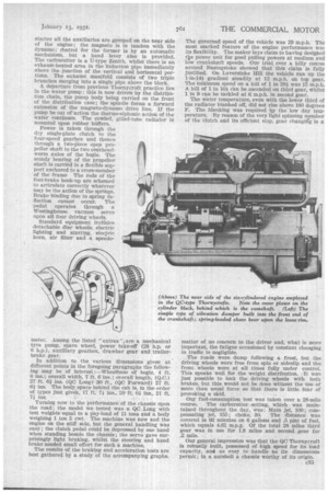
Without._ doubt the most striking feature about the chassis is the new NC/6-type engine, the leading figures in respect of whichwill be found in the accompanying panel. . The six cylinders are cast in one block, but there are two detachable heads; the bdrrels have dry; hard, cast-iron liners pressed into them. Actually forming a part of the block is the chamber for the camshaft ; this operates the side valves through roller-equipped rockers ; the camshaft is very accessible; by removal of the two covers its whole attendant mechanism can be inspected and adjusted. The distribution drive is by a triple-rolter chain; this serves all the auxiliaries, including the fan which has a clutch in its hub.
Seven white-metal-lined bearings carry the nickel-chrome-steel crankshaft ; between the front main bearing and the first big-end there is a vibration damper; this forms the subject of an accompanying illustration. The crankshaft is hollow and is drilled to permit force-feed lubrication of the big-end bearings. The submerged oil pump feeds the main bearings and the camshaft ; the overflow from the bearings of the latter falls into troughs in which revolve the cams ; oil is thus flung on to the rockers and rollers, etc. The cylinder walls are lubricated by splash, as are the Allah-end bearings.
All oilways are cored or drilled in the engine and there is a very deep Auto-Klean filter, coupled to the clutch pedal, in addition to the diaphragm filter above the sump.
Drive for the oil pump is by skew gear from the camshaft; from the upper end of the vertical shaft runs the flexible drive for the enginespeed governor.
A point worthy of note is that the upper portion of the crankcase is ribbed right down to the depth of the bearing caps, which are of aluminium and secured by steel keeper plates.
With exception of the 12-volt starter all the auxiliaries are grouped on the near side of the engine; the magneto is in tandem with the dynamo; cbittrol for the former is by an automatic mechanism, but a hand lever also is provided. The carburetter is a U-type Zenith, whilst there is an exhaust-heated area in the inductionpipe immediately above the., junction of the vertical and horizontal portions. The exhaust manifold consists of two triple branches merging into a single pipe above the block.
A departure from previous Thornycroft practice lies In the water pump ; this is now driven by the distribution chain, the pump body being carried on the front of the distribution case; the spindle forms a forward extension of the magneto-dynamo drive line. If the pump be out of'action the therino-siphonic action of the water continues. The cowled, gilled-tube radiator is mounted upon rubber buffers.
Power is taken through the dry single-plate clutch to the four-speed gearbox and thence through a two-piece open propeller shaft to the two overheadworm axles of the bogie. The steady bearing of the propeller shaft is carried in a flexible support anchored to a cross-member of the frame The rods of the foot-brake hook-up are schemed to articulate correctly whatever may be the action of the springs. Brake binding due to spring deflection cannot occur. The pedal operates through a Westinghouse vacuum servo upon all four driving wheels.
Standard equipment incliales detachable disc wheels, electric lighting and starting, electric horn, air filter and a speedo meter. Among the listed "extras ".,are a mechanical tyre pump, spare wheel, power take-off (28 h.p. or 6 h.p.), auxiliary gearbox, drawbar gear and trailerbrake gear.
In addition to the various dimensions given at different points in the foregoing paragraphs the following may be of interest :—Wheelbase of bogie, 4 ft. 6 ins. ; overall width, 7 ft. 6 ins. ; overall length, (Q.C.) 27 ft. 61 ins. (QC Long) 30 ft., (Q(J Forward) 27 ft. 61 ins. The body, space behind the cab is, in the order of types just given, 17 ft. 71 ins., 20 ft. Oi ins., 21 ft. 71
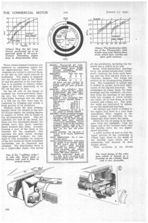
Turning now to the performance`of the chassis upon the road ; the model we tested was a QC Long with test weights-equal to a pay-load of 11 tons and a body weighing 1 ton 5 cwt. The machine was new and the engine on the stiff side, but the general handling was easy; the clutch pedal could be depressed by one hand when standing beside the chassis ; the servo gave surprisingly light braking, whilst the steering and hand brake needed small effort for such a machine.
The results of the braking and acceleration tests are best gathered by a study of the accompanying graphs. The governed speed of the vehicle was 29 m.p.h. The most marked feature of the engine performance was Its flexibility. The maker lays claim to having designed tDe power unit for good pulling powers at medium and low crankshaft speeds. Our trial over a hilly course around Basingstoke showed that this claim is fully justified. On Laverstoke Hill the vehicle ran up the 1-in-141. gradient steadily at 12 m.p.h. on top gear. The minimum speed on a hill of 1 in 281 was 15 m.p.h.
• A hill of 1 in 101 ean be ascended on third gear, Whilst 1 in 9 can be tackled at 6 m.p.h. in second gear.
The water temperature, even with the lower third of the radiator blanked off, did not rise above 160 degrees F. The blanking was required by the low day temperature. By reason of the very light spinning member of the clutch and its efficient stop, gear changitg is a
matter of no concern to the driver and, what is more important, the fatigue occasioned by constant changing in traffic is negligible.
The roads were damp following a frost, but the driving wheels were free from spin or sideslip and the front wheels were at all times fully under control. This speaks well for the weight distribution. It was just possible to lock the driving wheels with both brakes, but this would not be done without the use of more than usual force so that there is little fear of provoking a skid.
Our fuel-consumption test was taken over a 28-mile course. The carburetter setting, which • was maintained throughout the day, was: Main jet, 100;. compensating jet, 155; choke, 30. The distance was covered in 92 minutes on 6 gallons and .5 pint of fuel, which equals 4.62 m.p.g. Of the total 28 miles third gear was in use for 1.8 miles and second gear for .2 mile.
Our general impression was that the QC Thornycroft is robustly built, possessed of high speed for its load capacity, and as easy to handle as its dimensians permit ; in a nutshell a chassis wc)rthy of its origin.