


EQUIPMENT FOR GARAGE AND WORKSHOP.
Page 27
If you've noticed an error in this article please click here to report it so we can fix it.
Interesting Contributions from Three of Our Mechanic and Oliver Readers.
THERE IS no end to the list of equipment which can usefully be employed in the garage and workshop ; as a matter of fact, the chief task when considering such equipment is that of elimination,
Most workshops and garages are faced with the problem caused by the restricted space in which the work has to be carried out and, consequently, it is a bad policy to crowd in everything which may be useful.
From time to time on this page we have described various *articles which assist in the promotion of efficiency, but it is necessary that a careful choice be made.
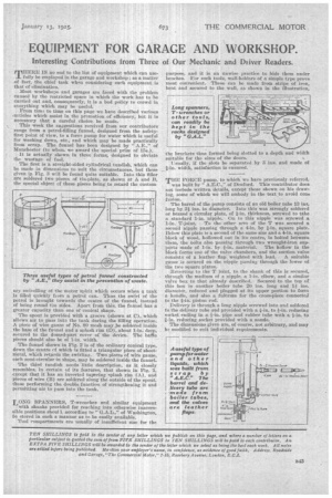
This week the suggestions received from our contributors range from a petrol-filling funnel, designed from the safetyfirst point of view, to a force pump for water which is useful for washing down, etc., and which may be made practically from scrap. The funnel has been designed by " A.E.," of Manchester (to whom we award the special prize of 15s.). It is actually shown in three forms, designed to obviate the wastage of feel.
The first is a straight-aided cylindrical tundish, which can be made in dimensions to suit the circumstances, but those given in Fig. 3 will be found quite suitable. Into this filler are soldered two pieces of tin-plate, as shown at A and E, the special object ef these pieces being to retard the custom.
cry swivelling ot the motor -spirit which occurs when a tank is filled quickly nem a petrol can. Thus the swirl of the petrol is brought towards the centre of the funnel, instead of being round the aides, Apart from this, the funnel has a greater capacity than one of conical shape.
The spout is provided with a groove (shown at C), which allows air to Pass into the tank during the filling operation. A piece of wire gauze of No. 80 mesh may _be soldered inside the base of the funnel and a splash rim (D), about 1-in. deep, secured to the domed-part cover of the device. The baffle pieces should also be of 1-in, width.
The funnel shown in rig. 2 is of the ordinary conical type, down the centre ef which is fitted a triangular piece of sheetmetal, which retards the swirling. Two pieces of wire gauze, each semi-circular in shape, may be soldered inside the funnel.
The third tnndish needs little description, as it closely resembles, in certain of its features, that shown in Fig. 1, except that it has an inverted tapering splash rim (A), and pieces of wire (B) are soldered along the outside of the spout, these performing the double function of strengthening it and permitting air to pass into the tank,
LONG SPANNERS, T-vp-renches and similar equipment with shanks provided for reaching into otherwise inacces eilele positions shout], according to " of Washington, be stored in such a manner as to be easilyavailable.
Tool compartments are usually of insufficient size for the purpose, and it is an unwise practice to hide them under benches. For such tool, wall-holders of a simple type prove most convenient. These can be made from strips of iron, bent and secured to the wall, as shown in the illustration, the brackets thus formed being slotted to a depth and width suitable for the sizes of the doors.
Usually, if the slots be separated by 3 ins, and made of _.a-in. width, satisfaction is ensured.
THEI FORCE pump, to which we have previously referred,
was built by " A.E.C.," of Deeford. This contributor does not include written details, except those shown on his drawing, some of which we will embody in the text to avoid cons fusion The.
of the pump consists of an old boiler tube 13 ins.
leng by 24 ins. iu diameter. Into this was strongly soldered or brazed a circular plate, Of 1-in, thickness, screwed to take a standard 1-in. nipple. On to this nipple was screwed a 1-in. T-joint, To the other arm of the T was secured a second nipple passing through a 4-in. by 4-in, square plate. Below this plate is a second of the same size and a 4-in, square block of wood, hollowed out in its centre, is bolted between them, the bolts also passing through two wrought-iron supports made of 1-in. by 4-in. material. The hollow in the block forms One of the valve chambers, and the suction valve consists of a leather flap weighted with lead. A suitable gauze is secured on the nipple passing through the lower of the two square plates.
Reverting to the I' joint, to the shank of this is secured, through the medium of a nipple, a 1-in, elbow, and a similar valve box to that already described. Secured to the top of this box is anether boiler tube 20 ins, long and 14 ins. diameter, reduced and plugged at its upper portion to form a handle, and also a fulcrum for the cross-piece connected to the 4-in, piston rod.
Delivery is through a long niPple screwed into and soldered to the delivery tube and provided with a 4-in, to reducing socket ending in a 1-in, pipe and rubber tube with a 4-in, to i-in, reducing socket provided with a nozzle.
The dimensions given are, of course, not arbitrary, and may he modified to suit individual requirements.