


A Resume of Recently Published Patent Specifications Anti-roll Suspension System
Page 54
If you've noticed an error in this article please click here to report it so we can fix it.
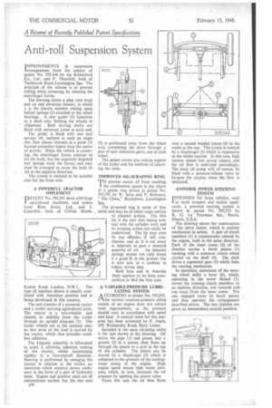
ImPROVEMENTS in suspension 'arrangements . form the 'subject of patent No. 593,344 by the Ribbesford Co., Ltd. and P. Thornhill, both of Tachbrook Road. Leamington Spa. The principle of the scheme is to prevent rolling when cornering, by resisting the centrifugal forces.
The drawing shows a plan viewjtop) and an end elevation (lower), in which 1 is the chassis member resting upon helical springs (2) attached to the wheel bearings. A rear girder (3) functions as a dead axle, holding the wheels in alignment. Both driving shafts are fitted with universal joints at each end.
The girder is fitted with two leaf springs (4), inclined at such an angle that their 'planes intersect at a point (5) located somewhat higher than the centre of gravity. When the vehicle is cornering, the centrifugal forces attempt to tilt the body, but the angularly disposed leaf springs resist the forces, and may even be arranged to cause the body to tilt in the opposite direction.
The system is claimed to be suitable also for the front axle.
A POWERFUL TRACTOR IMPLEMENT DATENT No. 593,58r deals with large agricultural machines, and comes from Blaw Knox, Ltd., and I. Conacher, both of Clifton House, Euston Road, London, N.W.I. The type of machine shown is usually associated with American practice and is being developed in this country.
The unit consists of a powered tractor and a trailer carrying agricultural tools. The tractor is a two-wheeler, and obtains its stability from the trailer through an upright king-pin (I). The trailer wheels are at the extreme rear, so that most of the load is carried by the tractor, which thus provides excellent adhesion, The king-pin assembly is bifurcated at point 2, allowing sideways rocking of the tractor, whilst maintaining rigidity in a fore-and-aft direction. Steering is performed by swinging the tractor in relation to the trailer, an operation which employs power assistance in the form of a pair of hydraulic rams. Engine and gearbox units are of conventional outline, but the rear axle a36 (3) is positioned away from the wheel axis, completing the drive through a pair of spur reduction gears, one to each wheel.
The patent covers also certain aspects of the trailer and the methods of adjusting the tools.
IMPROVED OIL-SCRAPING RING
T°prevent excess oil from reaching the combustion spares is the object of a piston ring shown in patent No. 593,392 by W. Sales and P. Hobourn, " The Chase," Blackdown, Leamington Spa.
The proposed ring is made of thin metal and may be of either angle section or channel section. The thin lip is the part that makes contact with the cylinder wall, and its scraping action can easily he understood. The lip may even be too elfectiv-: if left continuous, and so it is cut away at intervals to pass a metered quantity of oil. An inherent springy nature rot only keeps it a good fit in the groove, but it also acts as a cushion to reduce piston slap.
Both here and in America there appears to be keen competition to find the best type.
A VARIABLE-PRESSURE LUBRICATING SYSTEM
ACCORDING to patent No. 593,035, the normal constant-pressure oiling system ot an engine does not always meet requirements, as the pressure should vary in accordance with speed and load. A control valve for this purpose has been protected by F. Aspin, 149, Walmersley Road, Bury, Lancs.
Included in the main oil-pump outlet is the unit shoWn in the drawing. Oil enters the pipe (I) and passes into a groove (2) in a piston, then flows up through the piston to a port in the top of the cylinder. The piston can be moved by a diaphragm (3) which is subjected to the pressure of the coolingwater pump of the engine. High engine speed means high water pressure, which, in turn, increases the oil pressure by opening the piston valve.
From this unit the oil then flows
over a second waisted piston (4) to the outlet at the top. This piston is worked by a diaphragm (5) which is responsive to the intake suction. In this case, high suction means low power output, and the oil flow is restricted accordingly. The main oil pump will, of course, be fitted with a pressure-release valve to by-pass the surplus when the flow is restricted.
ANOTHER POWER STEERING SYSTEM I NTENDED for large vehicles, such as earth scrapers and similar appliances, a powered steering system is shown in patent No. 592,732 by R. G. Le Tourneau Inc., Peoria, Illinois, U.S.A.
The drawing shows the construction of the servo motor, which is entirely mechanical in action. A pair of clutch members (1) is continuously rotated by the engine, both in the same direction. Each of the inner cones (2) of the clutches carries a bevel pinion (3) meshing with a common crown wheel carried on the shaft (4). The shaft drives a segmental gear (5) which links the steering mechanism.
In operation, movement of the steering wheel shifts a lever (6), which, operating in the screw thread (7), moves the running clutch members in an endwise direction, one towards and one away from the inner cones. The one engaged turns its bevel pinion and thus operates the arrangement described above. The two clutches are given an intermediate, neutral position.