


Patents Completed.
Page 32
If you've noticed an error in this article please click here to report it so we can fix it.
Complete specifications of the following patents will be sent to any address in the United Kingdcast by the Sales Branch, Patent Office, Holborn, W.C., upon receipt of eightpence per copy.
Lubricating the Card-an Joint.
D'O. MeC. White and D. Napier and Son, Ltd., No. 331, dated 4th January, 1912.—Thin specification describes me
chanism by which efficient. lubrication el transmission device bearings, and like parts of compound shafts may be effected. Describing the invention broadly, when two shafts are subjected to any endwise relative movement, a hollow cylinder is formed or secured on one of them and a plunger on the other, to work in the cylinder, and to act as a pump. In the construction illustrated, the shaft is driven by the engine (not shown) from the right-hand end_ The drive is transmitted to a hollow shaft, on the left-hand end of which is fitted one of the elements of the c.ardan-joint ; the drive is effected by a castellated head on the end of the shaft engaging the interior of the hollow shaft. The pump cylinder is arranged inside the hollow shaft towards the left-hand end, and it communicates by means of suitable ducts with the bearings of the pins of the cardan-joint. The delivery valve on the pump is formed of a light steel spring, fitting closely round its left-hand end, which closes the port4 in that end on the 'suction stroke, and opens them on the delivery stroke. The plunger of the pump is formed as an extension of the solid shaft which is driven from the engine.
Wolseley's Sleeve-valve Gearing. The Wolselev Tool and Motorcar Cu., Ltd., and A. -A. Remington, No. 831., dated 11th January. 1912.-1n this
valve-gear a crank is provided on the half-speed shaft, and a rocking lever is mounted on this crank. The lower end of the lever is coupled by a link, set at an acute angle with a fixed point on the crankcase. The upper end of the lever is connected by a suitable link to the sleeve-valve, Owing to the rotation of the crank, the upper end of the lever is given the desired rise and fall for operating the valve, and at the same time it has a considerable lateral movement, owing to the lower end of the lever being held by the link to the crankcase; this lateral movement taking place on the end of each stroke of the valve. It will be seen, therefnre, that the valve is :ubstantially stationary during the compression and working strokes, but opens the ports very rapidly.
An Elastic Coupling.
Soc. Anon. des Automobiles et Cycles Peugeot, No. 29,232, dated under International Convention, 25th January, 1911. —This specification describes an elastic coupling for motor gearing in which the elastic member consists of a spring in the form of a cylindrical split ring. This surrounds the shaft, and is provided with two opposite lugs located on each end of the ring. These projections are engaged respectively by the driving and driven members. In lb. construction illustrated in the accompanying drawing, the driving member is formed on the huh of the fan-pulley, and it is coupled by the split-ring to the hub of a pinion loosely mounted on the crankshaft. 'Ibis pinion meshes with a gearwheel on a countershaft which it drives.
A New System of Balancing.
F. W. Laneliester, No. 26,038, dated alst November, 1911.—This specification describes a new method of balancing reciprocating engines, and more especially of eliminating the " secondary " vibrations to which twoand four-cylinder engines are subject. This is achieved by the provision of pairs of rotating bob weights which have twice the frequency of the piston or crankshaft motion. These weights are arranged to rotate in opposite directions, and are so positioned that they simultaneously neutralize the force due to the angularity of the connecting rod, and the alternating rocking movement consequent upon the changes in the kinetic energy of the pistons of the engine. This system of balancing lends itself to considerable variety of application. For example, it may be expedient in some cases to balance the torque in a negative sense, since the variable torque due to compression is, at
high speeds, greater than the torque due to the reciprocating masses. By means of the invention under notice it is possible to eliminate the resultant torque for any specified speed. If there is any critical speed with an engine at which vibration is set up in the chassis, the vibration can be neutralized at that particular speed, so that the synchronous vibrations of the engine and chassis are avoided.
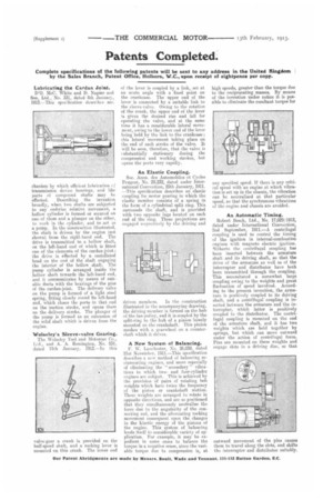
An Automatic Timing.
Robert Bosch, Ltd., No. 17,029;1912, dated under International Convention, 2nd September, 1911,—A centrifugal coupling is used to control the timing of the ignition in internal-combustion engines with magneto electric ignition. Ifitherto the centrifugal coupling has been inserted between the armature shaft and its driving shaft, so that the drive of the armature as well as of the interrupter and distributor have both been transmitted through the coupling. This necessitated a somewhat largo coupling owing to the weights and great fluctuation of speed involved_ According to the present invention, the armature is positively coupled to its driving shaft, and a centrifugal coupling is inserted between the armature and the interrupter, which latter is positively coupled to the distributor. The centrifugal coupling is mounted on the end of the armature shaft, and it has two weights which are held together by springs, but which can move outward under the action of centrifugal force. Pins are mounted on these weights and engage slots in a driving disc, so that outward movement of the pins causes them to travel along the slots, and shifts the interrupter and distributor suitably.