


Measurement of Crankshaft Mains Clearance
Page 56
If you've noticed an error in this article please click here to report it so we can fix it.
AANY a headache is caused in trans
IVI workshops when bottom-end trouble arrives, and a decision is needed to determine the true condition of main bearings and journals and their diametrical clearances. As the usual ailment is loss of oil pressure, a wrong decision can be expensive, very often calling for engine removal and overhaul. Other. than Leyland, who cater very satisfactorily with the problem of easy bearing change,. the engineer is usually faced with. crank grind, expensive bearings and a line bore; therefore assessment of .clearance and condition is critical and needs to be accurate.
Even in -this -day and age, it is truly amazing to see. the various attempts and methods used—with feeler blades, shim brass, and even pieces of cigarette packet, to determine mains clearance with the crank in place. Although it is a simple matter to ascertain big-end condition, this does not apply to main journals with only half of the shaft in view and, worse still, the crank, by reason of laying in the main-bearing caps, has concealed its clearance from normal sight and reach. The simple and accurate answer to this problem is the old but very reliable engineering method of taking "lead
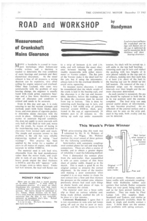
readings ". This practice has been applied by the writer for a number of years to al( makes of engine, with results accurate to within 00005 in.
The material used is soft lead wire, obtainable from the lead manufacturer rather than the motor trade, and available in reels of any thickness. For the heavy goods engine the ideal thickness is 0-030 in. and this will "squeeze" without danger, even to white metal. Under full bolt tension, the lead will flatten out
to a strip of between in. and I in.
wide, and will indicate the exact clearance between bearing and journal; readily measurable with either micrometer or Vernier caliper. The flat jaws of the Vernier make it the ideal tool for the job, but if using the micrometer, always turn it by the overload thimble to avoid extra squeezing.
To measure mains clearance, it must be remembered that the whole weight of the crank is laid in the bearing caps, and the clearance is at the top and inaccessible; therefore, before the readings can be taken the clearance must be moved from top to bottom. This is done by removing each bearing cap in turn, and inserting a full width strip of jointing material around 0.030 in. thick, positioned in the cap at approximately 20 minutes past to 20 minutes to'. On taking up each cap under reasonable
tension, the shaft will be moved up, a will settle in the top half bearings. removing each cap in turn and replaci the packing with two lengths of le wire placed radially in the cap and cic of oilways, making sure that each fen4 is at least in. short of the butt _fa, the bearing cap can be closed up unc full tension. On removal of the cap, t flattened strips can he measured intervals over their length and the ma mum clearance determined.
As each journal is measured, the pac ing should be replaced to hold the sh; in its top position until the exercise
complete. The lead strip can supt several useful pieces of information, the user becomes practised. An ex: reflection of the journal surface and cc dition can be seen on the strip and, used in big ends, both ovality and ,tat can be detected.