


A Novel Valve Layout P ATENT No. 784,945 discloses an engine
Page 78
If you've noticed an error in this article please click here to report it so we can fix it.
in which semi-rotary valves are used, and these can be arranged so as to give a longer expansion stroke than the inlet and exhaust strokes. (J. Hay, " Southlands," Sea Lane, Ferring, Worthing.)
The engine shown in the drawing is a two-stroke, but the scheme is equally applicable to four-strokes, with modifications. There are three sets of cylinder wall ports, controlling an exhaust belt (1) at the top, a high-pressure air belt (2) and a low-pressure belt (3).
The bottom row of ports is uncovered by the piston, but the middle and upper ones are controlled by slotted valve-sleeves (4 and 5). These are oscillated through a working angle by eccentrics (6 and 7) on a timing shaft.
In operation, the power stroke persists until the bottom row of ports is uncovered. When this occurs, the valve opens the top ports and a straight-through scavenge is obtained. On the up-stroke the high-pressure air valve opens and gives any desired degree of supercharge before being closed by the ascending piston.
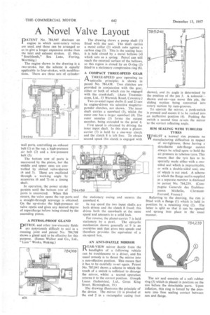
A PETROL-PROOF GLAND
DETROL and other low-viscosity fluids
are notoriously difficult to seal in a running joint and patent No. 784,708 shows a gland said to be effective for this purpose. (James Walker and Co., Ltd., " Lion" Works, Woking.) The drawing shows a pump shaft (1) fitted with the seal. The shaft carries a metal collar (2) which rubs against a carbon ring (3). This is the sealing face; it is held closed by a metal bellows (4) which acts as a spring. Petrol can still reach the external surface of the bellows, so this region is closed by an 0-ring (5) fitted in a stationary compression ring (6).
A COMPACT THREE-SPEED GEAR A THREE-SPEED gear operating on
epicyclic principles is shown in patent No. 784,438. Two clutches arc provided in conjunction with the gear, either or both of which can be engaged with the crankshaft. (Auto Transmissions, Ltd., 33 Warwick Road, Coventry.) Two co-axial input shafts (1 and 2) can be engine-driven via selective magneticpowder clutches, not shown. The inner shaft carries a sunwheel (3), whilst the outer one has a larger sunwheel (4). The outer annulus (5) forms the output member, being extended to the point 6.
First speed is obtained by driving the inner input shaft. In this state a planetcarrier (7) is held by a one-way clutch and the clutch 8 is left free. To obtain second speed this clutch is engaged with the stationary casing and secures the sunwheel 4.
In lop speed the two input shafts are both driven and the clutch 8 freed; this drives both the sunwheels at the same speed and amounts to a solid lock.
For reverse, the planet-carrier 7 is held stationary by a pawl. The epicyclic mechanism shown generally at 9 is an overdrive unit that gives two speeds and therefore provides the equivalent of a six-speed box.
AN ANTI-DAZZLE MIRROR
REAR-V1EW mirror dazzle from the headlights of a following vehicle can be troublesome to a driver, and his usual remedy is to thrust the mirror into a non-effective position. This means that it has to be carefully re-set again. Patent No. 785,041 shows a scheme in which the touch of a switch is sufficient to derange the mirror, whilst a second operation returns it to the correct position. (Joseph Lucas (Industries), Ltd., Great King Street, Birmingham, 19.)
The drawing illustrates the principle of the device. The mirror (I) is pivoted at the end 2 in a rectangular casing (not shown), and its angle is determined by the position of the pin 3. A solenoid— shown end-on—can move this pin, the sliding motion being converted into rotary motion by cam-grooves.
To operate the mirror, a push-switch is pressed and causes it to be rocked into -an ineffective position (4). Pushing the switch a second time re-sets the mirror to the correct reflecting angle.
RIM SEALING WITH TUBELESS TYRES
WHILST a normal rim presents no VV manufacturing difficulties in respect of air-tightness, those having a detachable side-flange cannot always be relied upon to hold the air pressure in tubeless tyres. This means that the tyre has to be specially made either with a onesided seal which is impracticable, or with a double-sided seal, one of which is not used. A scheme in which the flange seal is supplied as a separate member is disclosed in patent No. 784,239. (Cornpagnie Generale des Etablisscments Michelin, ClermontFerrand, France.)
Referring to the drawing, the rim is fitted with a flange (1) which is held in position by a retaining ring (2). The latter is split so that it can be opened and sprung into place in the usual manner.
The air seal consists of a soft rubber ring (3) which is placed in position on the rim before the detachable parts. Upon inflation, this ring is forced by the pressure into firm sealing contact between run and flange.