


Servo Cylinder for Hydraulic Brakes
Page 54
If you've noticed an error in this article please click here to report it so we can fix it.
A Resume of Recently Published Patent Specifications
DATENT No. 580,283 comes from L.
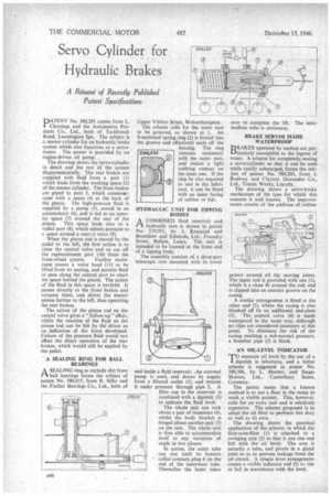
Chouings and the Automotive Products Co., Ltd., both of Tachbrook Road, Leamington Spa. The subject is a master cylinder for an hydraulic brake system which also functions as a servomotor. The power is provided by an engine-driven oil pump.
The drawing shows the servo-cylinder in detail and the rest of the system diagrammatically. The rear brakes are supplied with fluid from a port (1) which leads from the working space (2) of the master cylinder. The .front brakes ' are piped to port 3, which commusicares with a space (4) at the back of the piston. The high-pressure fluid is supplied by a pump (5), stored in an accumulator (6), and is led to an annular space (7) around the rear of the piston. This space leads also to a radial port (8), which admits pressure to a space around a central valve (9).
When the piston rod is moved by the pedal to the left, the first action is to close the central valve and so cut off the replenishment port (10) front the
front-wheel system. Further movement causes a valve head (11) to be lifted from its seating, and permits fluid to pass along the central port to reach the space behind the piston. The action of the fluid in this space is twofold. It passes directly to the front brakes and actuates them, and drives the master piston farther to the left, thus operating the rear brakes.
The action of the piston rod on the central valve gives a "follow-up" effect, whilst the reaction of the fluid on the piston rod can be felt by the-driver as an indication of the force developed. Failure of the pressure fluid would not affect the direct operation of the rear brakes, which would still be applied by the pedal.
A SEALING RING FOR BALL BEARINGS
A SEALING ring to exclude dirt from ft ball bearings forms the subject of patent No. 580,435, from R. Silby and the Fischer Bearings Co., Ltd., both of
Upper Villiers Street, Wolverhampton.
The scheme calls for the outer race to be grooved, as shown at I. An S-sectioned spring ring (2) is forced into the groove and effectively seals off the bearing, The ring remains stationary with the outer race, and makes a light rubbing contact on the inner one. If the ring be also required to seal in the lubricant, it can be fitted with an inner facing of rubber or felt.
HYDRAUL C UNIT FOR TIPPING BODIES
A—I A COMBINED fluid reservoir and
hydraulic ram is shown in patent No. 579,951, by J. Kinnaird and Bromilow and Edwards, Ltd., Foundry Street, Bolton, Lancs. The unit is intended to be located at the front end of a tipping body.
The assembly consists of a three-part telescopic ram mounted with its lower end inside a fluid reservoir. -An external pump is used, and draws its supply from a filtered outlet (1), and returns it under pressure through pipe 2. A filler cap in the reservoir is combined with a dipstick (3) to indicate the fluid level.
The whole unit can rock about a pair of trunnions (4), whilst the body bracket is hinged about another pair (5) on the ram. The whole unit is thus able to accommodate itself to any variation of angle in two planes.
In action, the outer tube can rise until its bottom collar contacts plug 6 on the end of the innermost tube. Thereafter the latter takes over to complete the lift. The intermediate tube is stationary.
BRAKE SERVOS MADE WATERPROOF
BDRAKES operated by suction are parLiticularly susceptible to the ingress of water. A scheme for completely sealing a servo-cylinder so that it can be used while totally submerged, forms the subject of patent No. 580,203, from J. Rodway and Clayton Dewandre Co„ Ltd., Titanic Works, Lincoln.
The drawing shows a servo-brake mechanism of the type for which this concern is well known. The improvements consist of the addition of rubber gaiters around all the moving joints. The input rod is provided with one (1), which is a close fit around the rod, and is clipped into an annular groove on the casing.
A similar arrangement is fitted at the other end (2), where the casing is also blanked off by an additional end-plate (3). The control valve (4) is made waterproof in the same way, although no clips are considered necessary at this point. To eliminate the risk of the casing reaching a sub-normal pressure, a breather pipe (5) is fitted.
' AN OIL-LEVEL INDICATOR
TO measure oil level by the use of a dipstick is laborious, and a better scheme is suggested in patent No. 580,306, by L. Shorter, and Singet Motors, Ltd., Canterbury Street, Coventry.
The patent states that a known method is to use a float in the sump to work a visible pointer. This, however, calls for an extra unit and is relatively expensive. The scheme proposed is to adapt the oil filter to perform this duty as well as its own.
The drawing shows the practical application of the scheme, in which the float-cum-filter (I) is attached to a swinging arm (2) so that it can rise and fail with the oil level. The arm is actually a tube, and pivots in a gland joint so as to prevent leakage from the oil circuit. A simple lever arrangement causes a visible indicator rod (3) to rise or fall in accordance with the level.