


BALANCING HOLLOW PROPELLER SHAFTS.
Page 64
If you've noticed an error in this article please click here to report it so we can fix it.
, A Resume of Recently Published Patent Specifications.
MILE name of Clarence W. Spicer, chief engineer of the 1 Spicer Manufacturing Corporation, of U.S.A., appears in connection with a machine and a method of balancing tubular propeller shafts in patent No. 279,951. The specification points out that, in balancing solid revolving bodies when a heavy place is found which causes a dynamic unbalance, it is usual to remove metal from that place generally by drilling holes or by grinding on an emery wheel. It is obvious that -uch methods cannot be carried out on a thin tubular member, so a theana is suggested of kinking the tube to bring all parts into running balance. The machine described, although speCially designed for the balancing of long and light shafts, does not differ in any material point from other balancing machines, a pointer being used to mark the revolving shaft where centrifugal force throws it nut of its usual course. No special device is described' for the operation of kinking.
The Suspension of Six-wheelers.
CERTAIN details connected with the suspension of the
axles of six-wheeler bogies are described in the specification of Charles Kearns Edwards and the Associated Equipment Co., Ltd., No. 280,047. The main feature of the invention appears to be the substitution of hall joints, similar to those used in steering rods, for the usual eye formed on the end of a spring. The springs are mounted parallel with each other, and are both pivotally attached to the vertical member which drops from the frame. The lower of these two pivots is, however, provided with a vertical as well as a horizontal pivot, and a certain amount of side-Play is allowed. The springs are formed so that they show taper in plan, being wide near the centre.
The Lubrication of Engine Parts.
A CURIOUS method of introducing oil to various work ing parts of engines is described in the specification of Clarence Eimer Bonner, of New -York, No, 279,995. The specification describes the use of porous metal for the actual bearing surface ; oil, being. introduced into grooves or recesses situated at the back of the metal which forms the hearing, is allowed to percolate through the pores a the metal and so reach the surface to be lubricated. Certain types of grey iron are suggested as being suitable. One of the main features of the invention which the in ventor claims as an advantage is that over-oiling is ilApossible with his system.
To Prevent Leakage Past Piston Rings.
IT is not often that we make mention of a patent NV hich
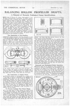
emanates from Spain, so that of Claudio Baradat and F. E. Anglada, of Barcelona, No. 262,716, is of more than usual interest. The inventors point out that the present method of construction generally adopted for piston rings is by no means perfect, as a hammering effect occurs at each stroke, first pressing the ring against one side of its groove and then against the other, this action being produced by the. friction of the ring against the wall of the 346 cylinder. Any slack that may develop and its groove is soon accentuated.
The present invention provides for two separate rings, both being in the same groove, one ring coming in contac6 with the cylinder wall and one side of the groove, .whilst the inner ring presses the outer one again'st the cylinder wall, and as its movement must stop there the jailer one makes a gastight seal between the conical face of the outer ring and the opposite side of the groove. Various applications of the plan are shown, the enlarged view making the working of the rinks clear, whilst the other views show the rings in different arrangements in pistons, and art alternative application where the grooves have angular faces. We remember seeing an arrangement of rings of a type resembling these fitted to the earlier models of Commer cars, but in that case there were three rings. The two outer rings came into contact with the cylinder walls, whilst the inner ring, whiLh formed a double cone, pressed the outer rings outwards until they met the cylinder walls and then forced then apart. 'From the results of wear it was evident that the rings in contact with the wall would set up sufficient friction to cause movement between them and the inner ring, thus defeating the object aimed at and causing disastrous wear. We would suggest that if the angle of the conical parts were 'reduced.to half that shown, namely, about 75 degrees with the axis, the trouble mentioned above could hardly occur.
Hydraulic and Mechanical Brake Operation.
BRAKES which can be operated by either mechanical or hydraulic means are described in the specification of the Christensen Air Brake Co., of Ohio, U.S.A. The shoes of this brake are provided at can end with the usual fiat eans which acts as a spreader and at the other end with a cylinder for fluid under pressure. By this method either end can act as a fulcrum, and either end can act as a means for spreading the shoes apart. Au anchorage is provided by links pivoted to the back plate. Specification No. 280,001.