


ALL SYSTEMS GO so long as they're drums
Page 36
Page 37
If you've noticed an error in this article please click here to report it so we can fix it.
by Graham Montgomerie
COMPARED with the car world, the commerical vehicle market has a wide variety of braking systems available. Hydraulic, air, a combination of both — all these can be found in vans and trucks sold in the UK.
So far as the brake assembly itself is concerned, the drum brake is supreme at the moment — a position it seems likely to retain for some time yet. Disc brakes are still confined to the light end of the vehicle range.
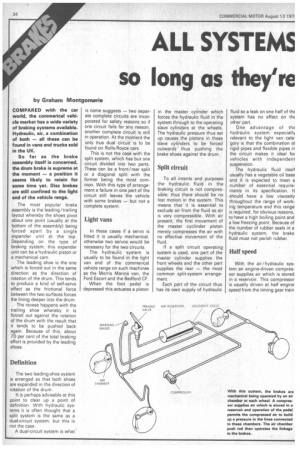
The most popular brake assembly is the leading/trailing layout whereby the shoes pivot about one point (usually at the bottom of the assembly) being forced apart by a single expander unit at the top. Depending on the type of braking system, this expander unit can be a hydraulic piston or a mechanical cam.
The leading shoe is the one which is forced out in the same direction as the direction of rotation of the drum. This tends to produce a kind of self-servo effect as the frictional force between the two surfaces forces the lining deeper into the drum.
The revese happens with the trailing shoe whereby it is forced out against the rotation of the drum with the result that it tends to be pushed back again. Because of this, about 70 per cent of the total braking effort is provided by the leading shoes.
Definition
The two leading-shoe system is arranged so that both shoes are expanded in the direction of rotation of the drum.
It is perhaps advisable at this point to clear up a point of definition. With hydraulic systems it is often thought that a split system is the same as a dual-circuit system, but this is not the case.
A dual-circuit system is what is name suggests — two separate complete circuits are incorporated for safety reasons so if one circuit fails for any reason, another complete circuit is still in operation. At the moment the only true dual circuit is to be found on Rolls-Royce cars.
This is not the case with the split system, which has but one circuit divided into two parts. These can be a front/rear split or a diagonal split with the former being the most common. With this type of arrangement a failure in one part of the circuit still leaves the vehicle with some brakes — but not a complete system_
Light vans
In these cases if a servo is fitted it is usually mechanical, otherwise two servos would be necessary for the two circuits.
The hydraulic system is usually to be found in the light van end of the commerical vehicle range on such machines as the Morris Marina van, the Ford Escort and the Bedford CF.
When the foot pedal is depressed this actuates a piston in the master cylinder which forces the hydraulic fluid in the system through to the operating slave cylinders at the wheels. The hydraulic pressure thus set up causes the pistons in these slave cylinders to be forced outwards thus pushing the brake shoes against the drum.
Split circuit
To all intents and purposes the hydraulic fluid in the braking circuit is not compressible; thus there should be no lost motion in the system. This means that it is essential to exclude air from the fluid as air is very compressible. With air present, the first movement of the master cyclinder .piston merely compresses the air with no effective movement of the fluid.
If a split circuit operating system is used, one part of the master cylinder supplies the front wheels and the other part supplies the rear — the most common split-system arrangement.
Each part of the circuit thus has its own supply of hydraulic fluid so a leak on one half of thc system has no effect on the other part.
One advantage of the hydraulic system especially relevant to the light van category is that the combination or rigid pipes and flexible pipes in the circuit makes it ideal for vehicles with independent suspension.
The hydraulic fluid itself usually has a vegetable oil base and it is expected to meet a number of essential requirements in its specification. It should have a low viscosity throughout the range of working temperature and this range is required, for obvious reasons, to have a high boiling point and a low freezing point. Because of the number of rubber seals in a hydraulic system, the brake fluid must not perish rubber.
Half speed
With the air/hydraulic system an engine-driven compressor supplies air which is stored in a reservoir. This compressor is usually driven at half engine speed from the timing gear train at the front of the crankcase.
When the driver presses the pedal, a valve is opened which allows the stored-up air pressure to exert a force on the air-chamber diaphragm which operates the master cyclinder as in the case of the basic hydraulic layout.
Compressed air
In the full hydraulic case the driver's foot does all the work; with the air/ hydraulic system, the driver's foot merely releases the air pressure to operate the hydraulics.
The Airpak system, which is not very popular these days but can still be found in service, retains more of the hydraulic system of operation. In this case the hydraulic pressure feed from the master cylinder (which is connected directly to the foot pedal) is boosted by the Airpak servo unit before .being supplied to the wheels.
The majority of heavy trucks — whether rigids or tractive units — and psv use a braking system which is operated entirely by compressed air. To prevent wear on the compressor and also overheating, the design of the system incorporates a method for taking the load off the compressor when the tanks are full.
In one case, a valve causes the compressor to be opened to atmosphere when the optimum reservoir pressure is reached; in the other method the compressor inlet valve is held open when the piston is on the compression stroke thus preventing movement of the air.
Safety valve
When the pressure in the tank falls, for example after using the brakes, the inlet valve is released and the compressor operate as normal. A safety valve is usually fitted to the delivery valve which blows off at around 1,030kN/ sg m (150psi) should the governor not operate. The pressure in the tanks is usually set at around 760 /830kN/sw m (110/ 120psi).
Air contains a considerable amount of water vapour which tends to condense in the reservoir. If this is not removed, fouling of the various valves in the system can occur and, of course, water can freeze which does not help the braking efficiency one little bit. To get rid of the water, all the tanks are fitted with drain cocks at the lowest point although several manufacturers fit chemical driers in the system to prevent the condensation occurring in the first place.
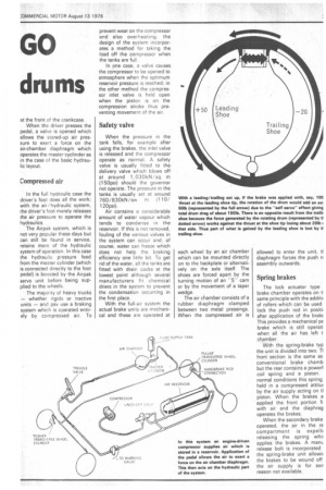
With the full-air system the actual brake units are mechanical and these are operated at each wheel by an air chamber which can be mounted directly on to the backplate or alternatively on the axle itself. The shoes are forced apart by the turning motion of an "S" cam or by the movement of a taper wedge.
The air chamber consists of a rubber diaphragm clamped between two metal pressings. When the compressed air is allowed to enter the unit, tl diaphragm forces the push n assembly outwards.
Spring brakes
The lock actuator type brake chamber operates on tl same principle with the additil of rollers which can be used lock the push rod in positil after application of the bralo This provides a mechanical pa brake which is still operati when all the air has left t chamber.
With the spring-brake typ the unit is divided into two. TI front section is the same as conventional brake chamb but the rear contains a powerf coil spring and a piston, normal conditions this spring held in a compressed attitu( by the air supply acting on tl piston. When the brakes a applied the front portion fi with air and the diaphrag operates the brakes.
When the secondary brake operated, the air in the re compartment is expellE releasing the spring whi( applies the brakes. A manu release bolt is incorporated the spring-brake unit allowir the brakes to be wound off the air supply is for son reason not available.