


Lubrication Systems for Commercial Vehicles.
Page 3
Page 4
If you've noticed an error in this article please click here to report it so we can fix it.
Ryknield, Lotis, Dennis, Commer Car, Wolseley-Siddeley, and Straker-Squire types.
(Continued from page 505.) Our preliminary classification of the different methods of lubrication, which are in use on modern, commercial, motor vehicles, provided for the separation of (b) the combined mechanical feed and splash system and (c) the splash system with mechanically-fed crank-chamber troughs, inasmuch as the two types embodied distinct principles; we shall, however, content ourselves by considering specific examples of these two sections under the one heading which follows.
Mechanically-controlled Splash Systems.
Early in this series of articles, we drew attention to the manner in which designers are now attempting to combine the undoubted thoroughness of the older splash system with the certainty of supply that arises from the employment of suitable mechanical feeds. Very interesting, indeed, from constructors' and users' points of view, are the ingenious methods, which have been evolved, with the object of securing a mechanically-controlled splash—or its equivalent spray—system, by the RykMeld Motor Company, Limited, Dennis Brothers, Limited, Sturrney Motors, Limited, Sidney Straker and Squire, Limited, and Commercial Cars, Limited.
The Ryknield Company provides for the efficient lubrication of its engines by a combination of two systems : we have already illustrated the general arrangement of the scheme on page 489 ante. The crank-chamber base has a deep well cast in it, and located therein is a small oil pump, or the conventional toothed-gear-wheel type, which is driven from the timing gear by a horizontal spindle lying inside the case. The depth of the base casting is such that a normal oil-depth of half an inch should be retained below the rotating big ends. The suction pipe from the pump draws the oil from the sump, into which it has settled, through a gauze strainer, forces it up to the reservoir on the dashboard and thence through a number of sight-feed glasses, down into the camshaft casing, which is thus con
stantly kept flooded. This casing, which forms an integral part of the crank-chamber casting, serves as a small reservoir from which a stream of oil is allowed to fall continuously on to each of the four big-ends, and, by way of suitably-inclined ducts, in to the two, central, crankshaft bearings : the two, end, main bearings receive their quota of oil direct, by gravity, from the dashboard reservoir. It will thus be seen, that the big ends, as they turn, receive a shower of oil every time they pass beneath the camshaft casing, and this spraying effect is found to be quite sufficient to ensure satisfactory Jubrica_ tion of both the pistons and the gudgeon pins, At first thought, one is inclined to question the necessity for the dashboard reservoir ; it would seem sufficient to have ensured that the camshaft casing, whicit acts as the auxiliary reservoir, should always be flooded direct from the pump, but the maker considers the inclusion of the sight-feed fitting to be a valuable assurance that the engine will not be unwittingly run if the pump has temporarily ceased its functions. In the unlikely event of the pump's incapacity, the construction of the base, and the arrangement of the ducts, on the Ryknield engine renders it an easy matter to fall back on the more ordinary splash system, by the simple process of pouring more oil into the crank chamber, and so raising the oil level. An auxiliary oil tank is carried on the dashboard, in order that fresh oil may be run direct into the crank-chamber.
In the previous article of the present series we illustrated the arrangement adopted by Sturmey Motors, Limited, of Coventry, for the lubrication of the engine on its " Lotis " chassis. The installation provides for the spraying of the big ends, the lubrication of the gudgeon pins and the main bearings by " splash," and of the pistons and cylinder walls by " forced feed." The system adopted, in this instance, is, therefore, a combination of various known methods, although, from the standpoint of the lubrication of the connecting-rod big ends, it can only strictly be classified as a " spray " system. On the Lotis engines, oil is, in the first place, fed by gravity, at a pre-determined rate from the dashboard reservoir through a sight-feed, into the crank chamber, and it is subsequently splashed round by the internal flywheels which practically fill the inside of the case. A sump is provided at the side of the case, and not at the bottom, as is the more usual custom, in order that excessive straining of the oil may not be necessary. From this sump, oil is sucked by a small pump, and it is then forced to a distributor, where it enters, in turn, three pipes, two ot which lead to the thrust sides of the cylinders, whilst the third directs a spray of oil on to the connecting-rod big ends, which are suitably grooved to receive the lubricant, The spray system has, in a modified form, been adopted on certain models, of which we may quote the Argyll.
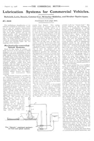
The Dennis Company, on its most recent models, has adopted an ingenious method by which the advantages of both the force-feed and the splash systems are retained : we illustrate here, by means of a diagram, the general arrangement of the parts. A small, duplex, gear-type, oil pump (E) is provided, and this has to perform two entirely separate functions. In the first place, one part of the pump forces the oil—as it overflows from the crank chamber—up into the reservoir (F), which is carried on the dashboard ; the oil is then fed by gravity from this reservoir into the other part of the pump, and thence forced up through suitable leads (D) into troughs, which are situated over the main bearings. From these troughs, the oil falls on to the bearings, through suitable holes, by gravity. The big ends (B) are lubricated by a splash system, which, however, is controlled by a constantly-maintained level. The oil (H) in the base, which collects from the various bearings and other moving parts, only rises to the height of an overflow dam, and then flows back to the first portion of the pump, which we have already mentioned. Filter gauzes are fitted in the tank, above the outlet to the pump, and the tank has the usual screwed 'cap for replenishment of the supply. It will be seen that, by this means, a definitely-determined level of oil can be maintained under the big ends, and this is controlled by the action ef the pump, which immediately returns any surplus of oil to the reservoir.
A method of securing this latest form of constant-level splash lubricati cm ; and
one that is more advanced, has for a long time been a feature of the vehicles produced by Commercial Cars, Limited. The small sketch which we reproduce will render the method adopted by this company quite clear to our readers. It will be seen that, in the lower part. of the crank chamber, a rump is formed in the main rasing, and this is of sufficient capacity to carry a full-day supply of oil for the engine. A small Albany pump, which is driven by a suitablydisposed worm gear from the camshaft, draws a constant supply of oil from the bottom of the sump through a lifter,. and forces it up a pipe which leads to a glass-faced box fixed on the dashboard. The whole of the discharge of this oil gravitates through the glass box, where it is clearly visible, down through another pipe into a duct (A), which is formed in, and runs the whole length of, the crank case. Transverse ducts (B) lead to four, boat-shaped troughs (C), which are situated immediately below the connecting-rod big ends. These troughs are narrow, and are of just sufficient size to allow the SCOOPS on the rod ends to dip well into them. A constant supply of oil is maintained to the troughs, and this is always in excess of what the scoops can remove; consequently, a continuous overflow is always taking place from the troughs back to the sump. Similarly, the oil which is, in the nature of things, always being splashed about the inside of the engine ease, slowly draining back into the sump. The filter at the base of the crank chamber is removable, and this will be found to be a great convenience when it is necessary, at intervals, to clean out the inside of the crank chamber. A spring valve is provided, so that the filter can be removed without the escape of the whole of the on. Should it he necessary to remove the oil, the valve can be kept open by the insertion of a rod or a piece of wire. The glass " " is of unusual size and construction, and it is in such a conspicuous position, clear above the top of the dashboard, that no driver could fail to observe it if the tell-tale ceased work. A tall pipe, which rises from the engine case, is fitted with a funnel at the top, and acts in two capacities, i.e., both as a vent ard as a filler. Com
mercial Cars, Limited, makes it a boast that, since the company introduced this method of lubrication, it has not known an instance in which a big-end bearing has given out, and we think that, when such a claim can be substantiated, as this one can, very little more need be said in favour of a system which yields such a satisfactory result : we are ourselves able to testify that another advantage, which accrues from the employment of this or similar methods, when an engine so fitted is in service, is the entire absence of exhaust.
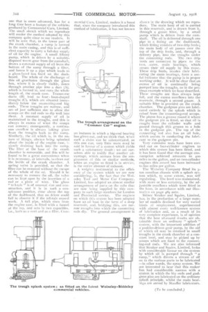
A weighty testimonial to the efficiency of the system which we are now considering, is, the fact that the Wolseley Tool and Motor Car Company, Limited, has adopted an almost similar arrangement of parts on the cabs that are now being supplied by this company in such large numbers for London and Provincial service. The engines on which this system has been adopted have an oil base in the form of a deep reservoir, and, bridging this, are narrow troughs into which the connecting rods dip. The general arrangement is
shown in the drawing which we reproduce. The main booy of oil is carried in this reservoir, and is drawn from it, through a gauze filter, by a small pump which is driven from the camshaft. The oil is delivered through one pipe to a fitting on the dashboard, which fitting consists of two drip feeds; the main body of oil passes over the top of the drip feeds, and, through a delivery pipe, into the troughs under the connecting rods. The two drip feeds are connected by pipes to the two, outer, main bearings, which secure their oil supply by this route. These drip feeds, besides their lubricating the main bearings, form a useful indicator that the pump is in proper working order, It will be clear that an excess of oil is continually being pumped into the troughs, As in the previous example which we have described. These troughs are thus always kept full, and the excess overflows into the reservoir, through a second gauze. A suitable filler is provided on the crank chamber. The gudgeon pins are lubricated entirely by the splash which is raised from the connecting-rod scoops. The piston has a groove round it where the gudgeon pin is fitted, so that oil is caught from the cylinder walls and passed through this groove to a hole in the gudgeon pin. The top of the connecting rod also has an oil hole, which assists in conducting the lubricant to the gudgeon pin.
Very extensive tests have been carried out on four-cylinder engines to which this system has been fitted, and it has been found that the average consumption achieved amounts to 400 miles to the gallon, and on two-cylinder engines this record has been increased to tioo miles per gallon.
The Wolseley Company fitted its 3ton omnibus chassis with a splash system which, to some extent, was sell regulating. The level was maintained, with more or less certainty, by the adjustable overflows which were fitted in the base, in accordance with out. illustration on page 489 ante.
Sidney Straker and Squire, Limited, has, in the production of a large number of models destined for very varied kinds of employment, experimented with almost every well-known system of lubrication and, as a result of its very complete experience, is of opinion that the hest all-round results are obtainable from an ordinary " splash " system, with the important addition of
positive-driven gear pump, by the aid of which oil may be retained in small troughs in the crank chamber at a constant level, and may be picked up by scoops which are fixed to the connecting-rod ends. We are also informed' that Straker and Squire, Limited, looks with considerable favour on the system by which oil is pumped through "a ramp," which directs a stream of oil. on to the various parts to be lubricated —in other words, the spray system. We are interested to hear that this maker. has had considerable success with a system in which the big-, ends and gudgeon pins are lubricated on the ordinary splash principle, whilst the main bearings are served by Stauffer lubricators..