


Rubber Torsion Springs P ATENT No. 676,098, comes from A. Moulton
Page 56
If you've noticed an error in this article please click here to report it so we can fix it.
and George Spencer Moulton and Co., Ltd., 13-14, Ashley Place, London, S.W.1, and shows the latest ideas on using rubber as a suspen
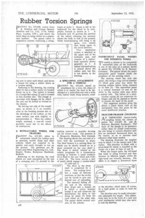
sion medium. The patent refers to suspention systems employing a swing mg arm to carry each wheel, and shows a means for using a rubber sleeve as a torsion spring.
Referring to the drawing, the rocking shaft (1) has a rubber sleeve (2) bonded firmly on to it. The rubber is housed in a:trough-like casing (3) and is bonded to this member also. The trough is provided with flanges (4) by which the unit can be bolted or riveted to the chassis.
By leaving one side of the trough open, as shown at 5, no troubles arise in the bonding process due to the shrinkage of the rubber, as the open surface can sink slightly to accommodate it. Were the rubber totally enclosed, a tear-off would probably occur due to the effects of contraction.
A RETRACTABLE WHEEL FOR TRAILERS
DATENT No. 675,307, refers to
retractable wheels for trailers such as caravans, mobile shops and other vehicles which are required to be quickly and easily brought to rest on the ground. The patentees are M. Green and Ibbett Engineering Co., Ltd., Stanley Works, Kempston Hardwick, Bedford.
• Referring to the drawing, the road wheels are each journalled on the end of a swinging arm (1) pivoted to the frame at point 2. Room is left in the bodywork for the wheel to be com pletely housed as shown at 3. A hydraulic jack (4) governs the position of the wheel; releasing the pressure allows the body to sink to the ground, whilst hand-pumping will bring it up again, t h e vehicle then being again in the travel position.
Th e suspension system is attached to the upper end of the hydraulic jack, and consists of a rubberbush assembly shown generally at 5. A helical rebound-spring is placed above the rubber unit, but this is not shown in the drawing.
A SPREADING ATTACHMENT FOR A VEHICLE
PATENT No. 675,619, shows an attachment for a lorry the object of which is to enable the load to be discharged at a controlled rate over a wide area, typical loads being manure, road
making material or possibly de-icing salt for frozen roads. The patentee -is F. Musgrove, Blenheim, New Zealand.
The drawing shows the rear-end of a lorry with the attachment in place. The chief feature is a moving floor (1) which can be slowly wound on to a drum mounted on the rear shaft 2. The drum is slowly rotated' as the vehicle progresses by a transmission working as follows: a small crankpin (3) is fixed to the rear wheel and rocks a lever (4). The latter carries a pair of pawls which engage a ratchet-wheel (5) and tun it.
The drive to the drum shaft is completed by a chain. The rocking lever has a range of fulcrum positions, so that the stroke can be varied to give any desired rate of unloading.
The material falling off 2 the end of the moving floor drops into a hopper (6) hi which a rotary member breaks it up and evens-out the distribution, the drive to this being by chain (7) from the road wheel on the other side. The patent shows several variants of the scheme.
INSTRUMENT PANEL WITHIN THE STEERING WHEEL
TO enable a chassis to be completely assembled clear of the bodywork is one of the aims of a scheme shown in patent No. 675,928, by B. Barenyi, Germany. The patent shows the entire instrument panel located inside the periphery of the steering wheel.
The steering wheel has only one spoke, this being a long curved member (1) which goes some way down the steering column before being clamped to its tube (2). The instrument panel is a conical structure (3) and all the wires to the various units pass down a central tube. The halves of a semicircular casing (4) are connected by hinges and can be opened as shown to expose the back of the panel.
The suggested position gives the driver a much better view of the instruments than that given by the usual dashbciard location.
TRACTOR-TRAILER COUPLING
A N IMPROVED tractor-trailer
rt coupling forms the subject of patent No 676,603 (K. and H. Schroter,. Bielefeld, Germany). The basis of the design is its geometry rather than. its actual construction, the aim being to convert drawbar pull into an increased downward force on the tractor, so as to increase road adhesion when most needed. • The drawing illustrates the simplest case in which 1 is the tractor and 2 the trailer. Thedrawbar is-fitted with a pivot-head (3) which is attached to the trailer via a pair of links (4 and 5).
When the tractor pulls, the left-hand link tends to swing forward and thus increase its effective length, whilst the right-hand one virtually shortens. The effect is to impart a downward force to the drawbar, which must, of course, be a rigid girder in order to load the tractor.
The drawbar may be made telescopically adjustable for length. This adjustment may be in the form of a rack and pawl mechanism which may also serve to lock the drawbar