


Three-wheeled One-cylinder Dumper
Page 34
If you've noticed an error in this article please click here to report it so we can fix it.
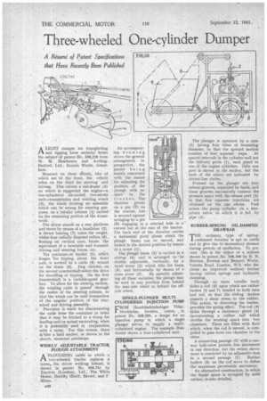
ALIGHT dumper tor transgorting and tipping loose material forms the subject of patent' No. 538,218 from -W. M. Henderson and Aveling
• Barford, Ltd., Invicta Works, Grantham.
Mounted on three v7hee1s, tWo of which are "at the front, the vehicle relies .on the third for steering and " driving. This carries a sub-frame (4) on which is supported the engine—a one-cylindered air-cooled two-stroke unit—transmission and winding winch .(3). the whole forming an assembly which can be swung for steering purposes, on a tubular column (1) carried' on the remaining portion of the frame_ work. -
The driyer stands on a rear platform and steers by means of a handlebar (2). A thrust bearing (7) takes the weight. Whilst four radially disposed rollers (8) ,. floating. on vertical axes, locate the equivalent of a turntable and transmit driving and steering forces, etc. „
The container•or bucket (5), which hinges, for tipping, about the front axle, is worked by a cable (8) wound on the drum (3). Dog clutches on the second countershaft select the drive for travelling or tipping. On the first dountershaft is a variable-speed gear'box. To allow for the steerims motion, the winding cable is passed 'through the centre of the steering column, so that the winch can be used irrespective of the angular position of the rearwheel and driving assembly.
r Provision is made for disconnecting the cable from the container in order that it may be hitched to a scoop for loading and/or actual excavating, when it is preferably used in conjunction with a ramp. For this reason, there is'also a land anchor, as shown in the , sketch, mounted amidships.
WIDELY ADJUSTABLE TRACTOR PLOUGH ATTACHMENT
A 'PLOUGHING outfit in which a J-1 two-wheeled tractor replaces a horse, the driver walking behind, is shown in patent No. 538,741 by 'Tractors (London), Ltd., The 'White House, Bentley Heath, Barnet, and F. Mines. •
An accompanying drawing shows the general arrangement in perspective, the patent being mainly concerned with the means 'for adjusting the position of the plough with ,re spect ' to the tractor. The drawbar pivots on a pin (7) on the tractor, but is secured against swinging by a pin (6) engaging in a selected hole in a` curved bar at the rear of the tractor. The back end of the drawbar carries a horizontal pivot about which the plough frame can be moved, and locked in the desired position by means of a screw (1).
The plough 'beam (5)' is carried in a stirrup 0) and is adranged to be
doubly adjustable, 'vertically, by a hand screw (2) which tilts the beam (5), and horizontally by rheans of a cross screw (3). By suitably adjusting all these variables, the plough may be used in any position from behind the near-side wheel to behind the offside wheel.
SINGLE-PLUNGER MULTICYLINDERED INJECTION PUMP 'ROM Handelsaktiebolaget Vidar, 1 Stockholm, Sweden,. comes„ in patent No. 538,293, a design for an injection pump in which. a single plunger serves to supply a multicylindered engine. The example illustrated shows a four-cylindered unit.
The" plunger is operated by a cam (2) having four lobes of increasing diameter, so that the upward motion consists of four, separate steps. At spaced intervals in the cylinder-wall are the delivery ports (1), each piped to one of the engine cylinders. Only one port is shown in the section, but the ends of the others are indicated by dotted-line circles. , Formed on the plunger are four release grooves, separated by lands, and these grooves successively connect the pressure space with the release port (3) so that four separate injections are obtained on the one stroke. Fuel enters the pump cylinder via a non.return valve, to which it is fed by pipe (9).
RUBBER-SPRUNG OIL-DAMPED DRAWBAR
THE ordinary, type of springcushioned drawbar is apt to rattle and to give rise to momentary stresses during periods of oscillation. To prevent this is the object of a scheme shown in pateni No. 538,186 by N. B. Newton, Newton and Bennett Works, Valetta Road, London, W.3,' who discloses an improved resilient towbar having rubber springs and hydraulic damping.
Through an outer tubufar body slides a rod (3) upon which are rubber bushes (2 and 7) bonded to both tube -and rod, so that the sliding motion imparts a shear stress to the rubber. This action, in distorting the bushes, provides the spring effect. The rod .(3) slides through a stationary gland (4) incorporating a rubber . ball which divides the working space into two chambers. These are filled with fluid which, when the rod is moved, is compelled to pass from one chamber to the other.
A connecting 'passage (s) with a oneway ball-valvepermits free movement in one direction, but the return movement is restricted by an adjustable leak in a second passage (1). Rubber buffers (6) on the rod serve to define the maximum permissible movement.
An alternative construction, in which the liquid space is occupied by solid rubber, is' also detailed.