


ENGINE LAYOUTS
Page 20
Page 21
Page 22
If you've noticed an error in this article please click here to report it so we can fix it.
As Qoverned by 'Fundamental
Principles of Balance
THERE are few automobile engineers who have not at one time or another been approached with such a poser as this: " Why is it not possible to have a three-cylindered engine to work as well as a four? " The person. asking such a question has not enough technical knowledge to enable him to understand a concise reply; otherwise he would not ask. To essay a reasonable explanation to. such a one is a lengthy business, because it is necessary to build up an elaborate framework of essential data upon which to formulate the answer.
The present purkse is to cover this essential groundwork in a logical sequence, aided by the use of practical analogies, such 'as can be comprehended by those not mathematically skilled. The treatment should prove of more than passing interest to technicians who may possibly have already experienced the difficulty of affording semi-technical explanations of this complex subject.
Basic Principles and Their Application
For the .appreciation of the methodically mtrided, these notes are divided into two main sections, the first in consideration of each of the basic principles of engine balance on individual merit, and the second—to appear in a later issue—in application of these principles to various forms of engine layout. .
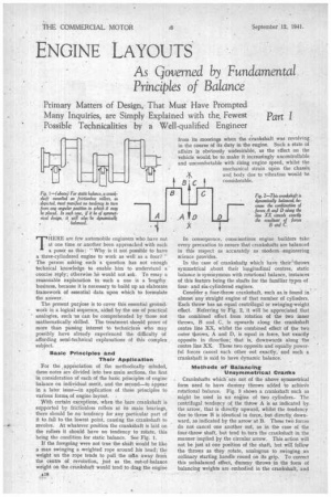
With certain exceptions, when the bare crankshaft is • supported by frictionless rollers at its main bearings, • there should be no tendency for Any particular part of it to.fall to the lowest point, causing the crankshaft to revolve. At whatever position the crankshaft is laid on the rollers it should have no tendency to rotate, this being the condition for static balance. See Fig. I. If the foregoing were not true the shaft would be like a man swinging a weighted rope around his head; the weight on the rope tends to pull the ncan away from the centre of revolution, just as the, out-of-balance weight on the crankshaft would tend to drag the engine from its moorings when the crankshaft was revolving, in the course of its duty in the engine. Such a state of affairs is obviously undesirable, as the effect on the vehicle would be to make it increasingly uncontrollable and uncomfortable with rising engine speed, whilst the mechanical strain upon the chassis 2F\ and body due to vibration 'would he
8 C considerable.
In consequence, conscientious engine builders take every precaution to ensure that crankshafts are balanced in this respect as accurately as modern engineering science provides.
In the case of crankshafts which have their 'throws symmetrical about their longitudinal centres, static balance is synonymous with rotational balance, instances of this feature being the shafts for the familiar types of fourand six-cylindered engines.
Conscder a four-throw crankshaft, such a& is found in almost any straight engine of that number of cylinders. Each throw has an equal centrifugal or swinging-weight effect. Referring to Fig. 2, it will be appreciated that the combined effect from rotation of the two inner throws, B and C, is upwards along the crankshaft centre line XX, whilst the combined effect of the two outer throws, A and D, is equal in force, but exactly opposite in direction; that is, downwards along the centre line XX. These two opposite and equally powerful forces cancel each other out exactly, and such a crankshaft is said to have dynamic balance.
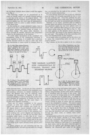
Methods of Balancihg Unsymmetrical Cranks Crankshafts which' are not of the above symmetrical form need to have dutritny throws added to achieire rotational balance. Fig. 3 shows a crankshaft such as might be used in nn engine of two cylinders.The centrifugal tendency of the throw A is as indicated by. the arrow, that is directly upward, whilst the tendency 'clue to throw B is identical in force, but directly downward, as indicated by the arrow at B. These two forces do not cancel one another out, as in the case of the four-throw shaft, but tend to turn the crankshaft in the manner implied py the circular arrow. This action will not be just at one position of the shaft, but will follow the throws as -they rotate, analogous to swinging an ordinary starting handle round on its grip. To correct this unbalanced effect, dummy throws in the form of balancing weights are embodied in the crankshaft, and the two-throw example shown below would then appear as in Fig, 4.
The balancing weights are sb proportioned as to create an exactly equal and opposite turning tendency to that due to the action of the original throw. The. crankshaft his now acquired perfect dynamic balance, and in a similar way any other type of unsymmetrical crankshaft would be made to rotate without vibration of the above type.
In the running of a single-cylindered engine, there is a space of one and a half crankshaft revolutions between each power impulse, reference being, of course, to a four-stroke design. The piston must, therefore, be driven through its exhaiist, induction and compression strokes by the momentum of the flywheel.
To avoid undue fluctuations of the crankshaft and transmission, owing to the considerable Variations in power supplied to them, it is needful that a relatively massive flywheel should be used in order that these large fluctuations in speed should be damped,down to within allowable limits. In the-case of a four-cylindered engine, there is a power impulse to the crankshaft every half-revolution, wherefore, by similar reasoning to the above, the flywheel need only 15e relatively small. Extending the discussion to engines of still more numerous cylinders, it will be obvious that, as the crankshaft increases its complexity of throws, so does the flywheel become smaller for the . same degree of freedom from torsional oscillation.
There are, of course, exceptions to the general principle, as with most axioms. A two-cylindered engine with side-by-side cylinders and cranks set at 180 degrees forms a typical example of the kind of exception to be expected in the present instance. The crankshaft is as shown in Fig.. 3, and assuming .fourstroke working and a power impulse just beginning on throw A the impulse on crank B can but begin half a revolution either before or after that of A. Conicquently, in each cycle of two complete crankshaft turns there are two impulses in one turn and none in the next; accordingly, a heavier flywheel would be required than if the design of the engine afforded evenly spaced power strokes.
A piston, gudgeon pin and connecting rod (the top part) do not'revolve, but move up and down in a straight line, as controlled by the walls of the cylinder. Such motion is termed reciprocating.
If a man smartly shoots one arm in and out, sideways from the body, it is virtually impossible for him to keep his body perfectly still. If -he then performs the exercise operating both arms at,the same time, he will find that his bady can easily be maintained quite stationary..
Similarly, in an engine, provision must be made to convene equal and opposite reciprocating actions. In a four-cylindered engine the two inner pistons move in unison, their combined effect being as if there was but one piston acting along the line XX in Fig. 5. The two outer pistons, in like manner, act as one at the centre line XX, but always in the opposite direction to the outer pair. The analogy of the man exercising with both arms simultaneously is now complete.
In an engine where an analysis such as the above can be made, the reciprocating parts are said to have primary balance.
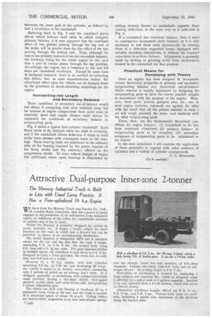
Fig. 6 shows, on the left, a piston in its two extreme positions, that is, at top and bottom dead centres. The right-hand diagram depicts the same piston exactly halfway along its stroke, for the centre of the connecting rod is coincident with the centre of the crank. The big-end can now be swung across on to. the crankpin circle, as indicated by the dotted line. It should be apparent that the piston will travel to the top from its .halfway position hi less time than it will travel to the bottom, bearing in mind, of course, that the rotational speed of the crankshaft is constant. The piston's speed is greater during the upper part of its stroke than during the lower part, and the force expended in stopping it at the top is greater than that in stopping it at. the bottom. Thus, the upward pull on the engine is always more than the downward pull when a piston is passing through top dead centre or bottom dead centre respectively. At half-cranked position the piston exerts neither pull not push on the engine, because it is being neither slowed nor accelerated when travelling at the same speed as the crankpin. The upward pull on the engine increases from nothing at half-crank to a maximum at top dead centre, and as the piston descends again to. . half-grank the upward pull decrea,ses again to zero. SiMilarly, the downward pull varies as the piston traverses the lower part of the cylinder, as defined by half a revolution of the crankshaft.
Referring back to Fig. 5 and the combined piston effects which balance each other to afford complete primary balance, it is now apparent that the combined effect of two pistons passing through 'the top end of the stroke will be greater, than the like effect of the two passing through the bottom end.. Thus, although the engine has primary balance it has not secondary balance, the tendency being for the whole engine to rise each time a pair of cranks passes through the top position. Accordingly the engine has a tendency to rise and fall twice per crankshaft revolution. ,Except by some form of harmonic balancer, there is no method of correcting this defect, but, as most manufacturers realize, the vibrational effect upon the vehicle can be damped down by the provision of shock-absorbing mountings ,for the engine. • '
Connecting-rod Length and Secondary Balance •
These conditions of secondary out-of-balance would not obtain if connecting rods were infinitely long, but for reasons of engine compactness these parts must be relatively short and engine designs must always be examined for conditions of secondary balance in reciprocating parts.
Fig. 2 shows a typical four-cylinder crankshaft. Each throw tends to fly outward when the shaft is revolving, and if the crankshaft allows deflection it tends to bend under these stresses with consequent loads on the bearings. These bearing loads are additional to the ordinary duty of the bearing imposed by the power impulse of the firing stroke and the resistance offered on the compression stroke. In more refined designs of engine this additional strain upon. bearings is eliminated by adding dumbly throws to crankshafts opposite ,those causing deflection, in the same way as is indicated in Fig. 4.
If a crankshaft has rotational balance, then it must in consequence incorporate static balance, so it is only necessary to test these units dynamically by rotating them in a delicately supported frame, equipped with suitable recording instruments, to indicate the required corrections to achieve balance. Adjustment is generally made by drilling or grinding metal from excrescences formed in the crankshaft for that purpose.
Practical Means for Complying with Theory
.Once an engine has been d'esigned to incorporate certain theoretical properties of primary and secondary reciprocating balance any theoretical out-of-balance which remains is usually minimized by designing the reciprocating parts to have the lowest possible weights in accordance with the purpose of the engine. Moreover, these parts, pistons, gudgeon pins, etc., are, in most engine factories, balanced one against the other with the result that all the pistons selected to form a set will weigh precisely the same, and similarly with the other reciprocating parts.
These," then, are the fundamental theoretical conditions for engine balance : (1) Crankshaft to be free from rotational vibrations; (2) primary balance of reciprocating parts to be complete; (3) secondary unbalance of reciprocating parts to be minimized to the utmost.
In the next instalment I will consider the application of these principles to engines with other numbers of cylinders and a variety of cylinder arrangements.
G. L. SITICLLEFE. (To beconcluded.)