


A SIMPLE SUSPENSION SYSTEM,
Page 30
If you've noticed an error in this article please click here to report it so we can fix it.
A Résumé of Recently Published Patents.
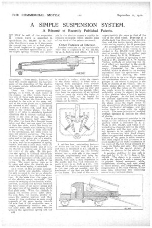
..MAY be said of the suspension 4 system which is described in 'specification No. 168,865 by R. Mervilla, that there is more in it than meets the eye—at any rate, at is first glance. On casual inspection it appears to be merely a modified application of quas-ter-elliptic springs without any special
advantages. Closer study, however, reveals that rather ingenious use has been made of the disposition of the shackles to acquire certain substantial and usefulproperties.
There are three quarter-elliptic
springs, as it were, at each corner of the chassis. In other words, there are two sets of three such springs to each axle. Of the three, the lowest is firmly attached to the axle at its -outer end, and at the ether pivots ;.on a horizontal pin secured to,the chassis. This spring serves as a radius rod, and does not bend in the vertical plane.. Its flexibility is of value in absorbing torsional vibrations due to uneven vertical movements of the ends of the axle. This spring has its longest leaf uppermost. The other two have their longest leaves below, and they rest one upon the other at their butt ends, which, are firmly secured to the chassis, the fastening beirg a special one, which is duly described in the specification, but with which we used not concern ourselves. The lower of these two springs is attached at its outer end to the upper pin of a shackle, the lower end of which is pivoted to the axle, and the arrangement of spring, shackle, and axle is such that, when the vehicle is normally loaded and at rest, the shackle is vertical and in line with the centre of the axle. In this peal
lion the spring is inclined downwards from she chassis to the shackle, so that any upward movement of the axle tends to increase the effective length of the spring. The upper spring rests as to its outer end upon the shackle pin to which the lower spring is attached.
As. a result of. this peculiar arrange
ment of spring and shackle, whenever the axle is caused to rise by an obstacle, it revolves slightiy in a clockwise direction. At the same time, the upper pin of the shackle moves outwards. This results in swinging of the shackle, which, however, is resisted by friction between the lower plate of the upper spring and. the upper pin of the shackle upon which that plate rests. Whets the obstacleis passed the reverse aetien takes place, the axle falls, the shackle quickly resumes the vertical position and then passes it, thus producing a more rapid approach of the upper spring towards the axle than if the conneetion were a simple, permanently vertical one. At the same time, the continued friction between the uppermost spring and the
pin in the shackle causes a rapidly increasing resistance which absorbs some of the shuck of the return movement.
Other Patents of Interest.
Another variation of the transferable body idea is explained in No. 183,499, by A. E. Jackson and others. The body
is actually a, trailer, while the chassis of the motor vehicle is fitted with a tipping body equipped with slidable oils_ When the body is tipped -these rails can be slid beyond its rear end until they rest upon the ground, wheu they form the equivalent of an inclined plane or ramp up which the trailer or transferable body can be hauled by means of a winch, with which the chassis can be fitted.
A rail-less bus, outstanding features of which are the low, level of its floor and seats, is described in No. 183,596 by R. Freeman. There are two driving motors, one at each side of the chassis, arranged longitudinally and lying beneath the seats. The rear axle is 17shaped, with such a deep depression in the middle that the road clearance beneath it may be as little. as 5 ins. The frame of the chassis is arranged as close to this rear axle as possible, and the floorboards of the bus are laid directly on the frame. The level of the seals is approximately the same as that of the top of the read wheel. Drawings of a double-deck bus illustrate the specification, and the design therein shown provides seating capacity for 62 passengers.
An arrangement of the two fore axles of a six-wheeled motor vehicle is described in No, 183,510 (with which we deal at greater length on another page us this issue), by R. H. Wilkinson. • Apeculiar system of Springiug, is embodied in No. 183,500, by A. W. Gattie. Various methods of achieving the desired effect are described in the specification. The principle, however, is' amply illustrated by the simplest method, which is shown in the drawing reproduced from the specification. Referring to this drawing, the lower shaded circle is the axle which supports the 'mechanism shown, The vertical plunger in the centre is coupled to the bocly.or chassis of the vehicle. The inclined planes shown are pressed into contact with the rollers on the ends of the toggle levers by springs which are sufficiently strong to support the levers in that position when a lead is applied to the plunger. As the load increases, the plunger approaches the axle, and, as will be apparent from the drawing, the planes cause the toggle levers t./.3 take up positions which afford the springs .better mechanical advantage, and thee enable them to cope with the added weight. The same prihciple of modified leverage operates to restrain the effect
of shocks. .
There is an important provision in the design of the auxiliary or supplemental gearbox which is described by E. T. Wade in No. 183,524, and which is intended to be disposed between the ordinary gearbox and the rear axle. The ,box appears to be particularly applicable in connection with Ford chassis; Means are provided whereby the neutral poeition of the gears is made unstable. The chief object of this provision is to avoid rendering the brake inoperative in the event of the box being arranged be. tweet the brake and axle.' This object is effected by the special design of notches, or grooves, in the selector rod.
A peculiar stabilizer for rear axle is
described by G. H. E. Ram in No. 166,534. The object is to connect the axle to the chassis in such a manlier as to prevent lateral' movement, while, nevertheless, allowing,: each road wheel to follow freely, and Independently, all irregularities of the road without, at the same time, subjecting this connecting means to any torsional strain.