


OVERHAULING THE KARRIER.
Page 21
Page 22
Page 23
Page 24
If you've noticed an error in this article please click here to report it so we can fix it.
No. 22.—The 45-50 h.p. 1{4-type. The Preliminary Dismantling, Disassembling, Inspecting and Taking Up Wear in the Units. Useful Tools and Gadgets.
IN THIS article we shall deal with the latest Karrier chassis in which an engine of the company's own make is utilized. Previous models acre fitted with Tyler engines, and instructions regarding the overhauling of these engines have appeared in connection with other chassis, particularly in No. 3, the A.E.C. In certain features the Li model is somewhat similar to its immediate predecessor, and users of the latter will undoubtedly find much of interest in the instructions given regarding the latest model.
Dismantling.
Assuming that the body and cab have been removed, turn off the petrol, drain the water from the radiator and undo the water connections, also tierod between the dash and the radiator, after the bonnet, which is held by a bolt at each end, has been removed.
The engine is three-point suspended in the frame, but before removing the supporting bolts the eardan shaft must be disconnected by taking out the coupling bolts of the Hardy disc joint, also disconnect the oil pipe, control rods, dynamo cable, petrol pipe and switch wire, whilst the exhaust manifold must be removed by.unbolting it and sliding it out of its sleeve-joint in the exhaust pipe.
Now remove the engine rear arm securing bolts and support the weight by means of a crane or suitable tackle. Having done this, disconnect the front cross member from the frame by taking out two bolts at each side, then, by tilting the engine up at the front end, it can be disengaged from the clutch forks witheut removing the clutch pedal gear. It is preferable to drop the undershield before commencing to lift. This shield is held in position by spring handles and can be drawn backwards and extracted at the side of the chassis bierween the front and rear wheels.
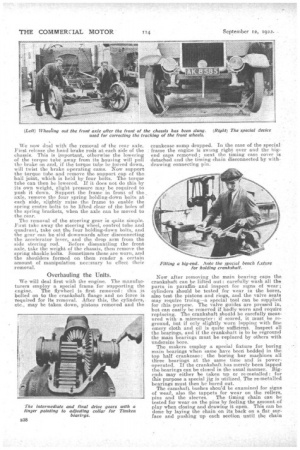
To take out the gearbox, uncouple the short eardan shaft at the rear of the gearbox. This can be removed without disturbing the latter or the torque tube, by taking off the brass dust cover and the bolts which secure the cardan shaft -universal joints. Having done this, force the rear universal joint backwards in order to clear one of the driving dogs. This movement will be about A in. and is allowed for in the splined muff coupling at the rear end of the long propeller shaft. Now disconnect the changespeed rods and thea foot-brake pull-rod, when, after removing the holding down bolts securing the gearbox to its cradles, lifting tackle may be brought into service and the box may be either lifted out or tipped and lowered between the cradles. We no* deal with the removal of the rear axle. First release the hand brake rods at each side of the chassis. This is important, otherwise the lowering of the torque tube away from its housing will pull the brake on and, if the torque tube be forced down, will twist the brake operating cams. Wow support the torque tube and remove the support cap of the ball joint, which is held by four bolts. The torque tube can then be lowered. If it does not do this by its own weight, slight pressure may be required to push it down. Support the frame in front of the axle, remove the four spring holding-doWn bolts at each side, slightly raise the frame to enable the spring centre bolts to be lifted clear of the holes of the spring brackets, when the axle can be moved to the rear.
The removal of the steering gear is quite simple. First take away the steering wheel, control tube and quadrant, take out the four holding-down bolts, and the gear can be slid downwards after disconnecting the accelerator lever, and the drop arm from the side steering rod. Before dismantling the front axle, take the weight of the chassis, then remove the spring shackle bolts. Sometimes these are worn, and the shoulders formed on them render a certain amount of manipulation necessary to effect their removal.
Overhauling the Units.
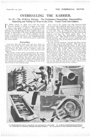
We will deal first with the engine. The manufacturers employ a special frame for supporting the engine. The flywheel is first removed: this .is bolted on to the crankshaft flange and no force is required for its removal. After this, the cylinders,etc., may be taken down, pistons removed and the crankcase sump dropped. In the case of the specialframe the engine is swung right over and the bigend caps removed ; next the timing case cover is detached and the timing chain disconnected by withdrawing connecting pin.
Now after removing the main bearing caps the crankshaft can be lifted out : carefully wash all the parts in paraffin. and inspect for signs of wear ; cylinders should be tested for wear in the bores, also test the pistons and rings, and the valve seats may require truing—a special tool can be supplied for this purpose. The valve guides are pressed in, but can easily be removed if badly worn and require replacing. The crankshaft should be carefully measured with a micrometer : if scored, it must be reground, but if only slightly worn lapping with fine emery cloth and oil is quite sufficient. Inspect all the bearings, and if the crankshaft is to be reground the main bearings must be replaced by others with undersize bore.
The makers employ a special fixture for boring main bearings when same have been bedded in the top half crankcase: the boring bar machines all three bearings at the same time and is poweroperated. If the crankshaft has merely been lapped the bearings can be closed in the usual manner. Bigends may either be taken up or re-metalled: for this purpose a special jig is utilized. The re-metalled bearings must then be bored out. The camshaft bushes should be examined for signs of wetut, also the tappets for wear on the rollers, pins and the sleeves. The timing chain can be tested for wear on the pins by feeling the amount of play when closing and drawing it open. This can be done by laying the chain on its back on a flat surface and pushing up each section-until the chain is made as short as possible:. its length should then be noted, after which the chain should. be stretched to its full limit of length; if this amount exceeds in. the chain should be reneWed or returned to the makers for re-pinning.. . The oil pump is of the gear type and can be taken down together with the water removing
by removin six nuts only : the drive is through an intermediate wheel off the camshaft, and when the pump is removed the drive disengages itself. The oil pump should be dismantled and inspected, but it is not likely that any repairs will be required. The oil filter is located in the near-Side rear engine arm and can be removed by unscrewing the brass knurled nut on bridge .piece, which piece can be turned in order to disengage itself from the two uprights. The filter can then be lifted out and all dirt and deposits should be removed from the filter and body. Also the gauze should be inspected to ensure that it is unbroken and sound, and the leather washer at the bottom of the cage should be examined. The water pump is of the ordinary centrifugal' type, driven from a flexible coupling. It is advisable to re-pack the glands with a special packing which can be obtained from the makers.
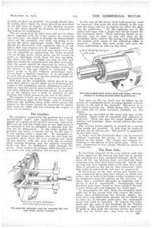
End play on the crankshaft, which should be not more than .010 in., can be taken up by deepening the recess in the crankshaft pinion, skimming it out in a lathe so that the pinion goes farther on to the shaft and thus tightens the thrust, ball races: it is driven on to the splines and is held in position by the starting dog which screws on the end of the shaft. The engine is built up in the reverse manner and when replacing same in the frame—and at frequent intervals—the holding down bolts which secure the engine to the frame should be inspected to ensure that same are tight and not allowing the engine to move on its bearers.
The Gearbox, •
The attention required by the gearbox has proved particularly slight, and replacements have been almost nil, except so far as ballraces are concerned. i However, incasethe latter may at any time have to be replaced it will be advisable to describe how the box can be dismantled. In the older models the gearbox was made in halves, but in the K4 type it is one casting with a large lid. To dismantle it, remove the brake shoe straps, also the nut from the secondary shaft, draw the rear coupling and drum off the splines, undo -the nuts from the secondary shaft bearing housing, and the eplined secondary shaft can then be withdrawn right through the gears. Next. remove the primary shaft bearing housing stud nuts and_withdraw the primary shaft. In the case of the latter shaft both housings mutt be removed, then slide the shaft slightly to the rear and the front end can be tipped up, when the shaft can be withdrawn. All the bearings are of the radial ball type with a single ball thrust washer for the secondary shaft. These bearings should be examined, and to ta,ke up any end play on the secondary shaft, reMove the spring ring which holds the locking grub screw of the adjusting collar in position. Loosen this grub screw and turn the collar sufficiently to take up the wear.
End play on the lay shaft can be taken up by means of a hardened screw pressing against a thrust button in the end of the layshaft. The screw is in , the front housing cap. While doing this, care must be taken not to cause excessive pressure on the button.
Glands are provided at the front and rear of the gearbox. These must be repacked and adjusted as required. There are also two small glands for the selector rod bearings; these should receive the same attention.
The reverse pinion spindle is secured by a spring ring inside the gearbox. If this ring be removed the pin can be driven out. The pinion is supported on two ball races.
If badly worn the foot-brake shoes can be renewed -without replacing the straps, as the shoes are bolted on the latter. The straps may require rebushing or the fitting of new pivot pins. After repair, adjustment is very simply effected by means of a wing nut.
The Rear Axle.
To facilitate removal of the rear wheels each has a hole tapped in the driving dog hub cap to permit the insertion of a fin. diameter setscrew, which will force off the cap (driving .dog), provided the three retaining nuts have first been' removed. Inside this driving cap is a locking collet with four dog teeth. This is secured to the nut. byfonr setscrews; after this collet; is removed the nut may be unscrewed. If lubrication of the rear spring seat•bushes has been neglected these may have seized, in which case either one or both of the. brake anchor brackets must be withdrawn from the splines on the axle bed. To effect this a powerful extractor ig required, and a sketch of this is reproduced.. 'Occasionally these brackets have been found to. have cracked through a stone flying into and jamming the brake gear. To disassemble the axle, draw; the propeller shaft right out of the torque -tube and remove the latter. Then, after withdrawing the . driving shafts, the final drive and differential gearing can be lifted out en bloc or, if thought preferable,-the cross-shaft cover only need be removed. TO remove the crossshaft ease the caps of the housings for the Timken bearings. This allows the crown wheel to come out of mesh so that both the driving pinion and crossshaft may be lifted out. Any wear on the cross shaft bearings can be taken up, as they are of the taper-roller type,1 but the bearings of the pinion shaft are of the radial ball type and, if badly worn, must be renewed. Double ball-thrust bearings are provided on the pinion shaft. Any slackness in these can be taken up by shortening the distance sleeve, by accurately grinding the ends. In adjusting the Timken bearings it should be observed that the locking nuts must be screwed outwards to the lock. The pinion bearings are posi
tively locked against the distance sleeve by a circular nut, held in position by a grub screw which is itself prevented from movement by a spring ring. The differential and final drive spur reduction wheel may be removed by taking off the bearing housing straps. The bearings are of the radial type
with single ball-thrust washers. If any end play has developed a thicker spacing washer should he fitted.
It is essential to pull the straps up tightly when reassembling, also make certain that the studs are tight and that all the nuts are well tightened and split-pinned. So far as the rear wheels are concerned, new floating bushes may be required. Side play can be taken up by means of the end nut. This makes up for any wear of the steel thrust washers.
The wheels themselves have steel liners pressed into position. In the event of these being worn they must be pressed out and renewed. In fitting a new
wheel liner do not fail to drill the grease hole, which must be done when the liner is in position. If too
much side play is allowed on the wheels, which only happens through gross neglect, the threads of the axle bed may be damaged, and, if so, it will be necessary to reserew them to fit an undersized nut. To effect this the makers will be pleased to loan a special die and can supply undersized nut. If the brake drums and shoes have become worn, special packing pads should be fitted to the brake
shoe straps, and, if necessary, the shoes themselves may be renewed.
The Front Axle.
If end play has developed in the front wheels this can be taken up by the fitting of oversized thrust washers, which will be supplied by the makers. New floating bushes may be required, also new Steel liners which are similar to those in the rear wheels. The stub axle pins are each secured.by acotter bolt, which must be extracted. To remove the pins they must be tapped downwards. Each has a ball-thrust washer at the top, and, if pitted, these washers must be renewed. The swivel arm bushes themselves are of hardened steel and very little wear occurs in them.
The reassembling of the chassis should be performed in a similar manner to disassembling, hut the procedure must, .of course, be reversed. It is unnecessary for us to enter into this matter in detail.
Alignment of Front Wheels.
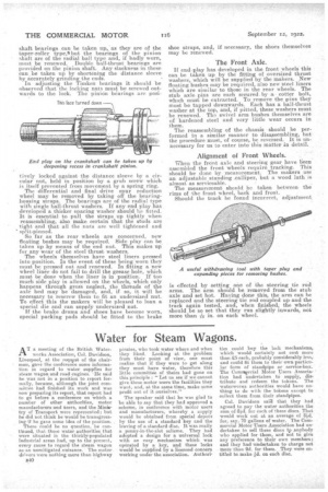
When the front axle and steering gear have been assembled the front wheels require tracking. This should be done bymeasurement. The makers use an adjustable standing ..calliper, but a wood lath is almost as serviceable.
The measurement should be taken between the rims of the front wheel, back and front.
Should the track be found incorrect, adjustment.
is effected by setting one of the steering tie rod arms. The arm should be removed from the stub axle and set hot. Having done this, the arm can be replaced and the steering tie rod coupled up and the track again tested, and, when finished, the wheels should be so set that they run slightly inwards, not more than -Ain. on each wheel.