


Patents Completed.
Page 20
If you've noticed an error in this article please click here to report it so we can fix it.
A Leyland Transmission Gear.
A. Fergusson, H. Spurrier and Leyland Motors, Ltd.—No. 17,186, dated 27th July, 191L—According to this invention the differential is arranged as usual at the end of the propeller shaft, but the live axles are dropped below the plane of the engine crankshaft, and the drive is transmitted to them from a short transverse shaft carrying the differential by pinions meshing with gearwheels on the inner ends of the two live axles. These gears may have slightly helical teeth to permit the mounting of the live axles with a slight downward slope. The live axles are carried on a dropped dead axle which also carries the casing for the differential. It will be seen from the drawings that by removing the side plates of this casing the whole of the gear is very accessible. An alternative construction is also described and illustrated in the specification.
Splash Lubrication.
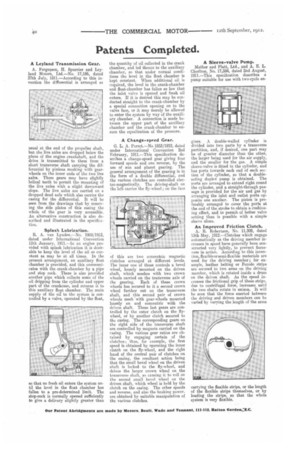
R. A. van Lynden.—No. 1008/1912, dated under International Convention 12th January, 1911.—In an engine provided with splash lubrication it is desirable to keep the level of the oil as constant as may be at all times. In the present arrangement, an auxiliary float chamber is provided, and this communicates with the crank-chamber by a pipe and stop cock. There is also provided another pipe which collects some of the oil dripping from the cylinder and upper part of the crankcase, and returns it to this auxiliary float chamber, The main supply of the off to the system is con trolled by a valve, operated by the float
so that no fresh oil enters the system until the level in the float chamber has fallen to a pre-determined limit. The stop-cock is normally opened sufficiently to give a delivery slightly greater than
the quantity of oil collected in the crank chamber, and led thence to the auxiliary chamber, so that under normal conditions the level in the float chamber is kept constant. When additional oil is required, the level in the crank-chamber and float-chamber has fallen so low that the inlet valve is opened and fresh oil enters. If it is desired this may be conducted straight to the crank-chamber by a special connection opening on to the valve face, or it may merely be allowed to enter the system by way of the auxiliary chamber. A connection is made between the upper part of the auxiliary chamber and the crank-chamber to ensure the equalization of the pressure_
A Change-speed Gear.
G. L. A. Perret.—No 1853/1912, dated under International Convention 2nd February, 1911.—This specification describes a change-speed gear giving four forward speeds and one reverse, by the use of sun and planet gearing. The general arrangement of the gearing is in the form of a double differential, and the various clutches are controlled electrosmagnetically. The driving-shaft on the left carries the fly-wheel ; on the face of this are two concentric magnetic clutches arranged at different levels. The inner one of these controls a bevel wheel, loosely mounted on the driven shaft, which meshes with two crown wheels carried on the transverse axle of the gearing. Each of these crown wheels has secured to it a second crown wheel further out on the transverse shaft, and this second pair of crown wheels mesh with gear-wheels mounted loosely on and concentric with the driven shaft. These last gears are controlled by the outer clutch on the flywheel, or by another clutch secured to the casing. The corresponding gears on the right aide of the transverse shaft are controlled by magnets carried on the easing. The various gear ratios are obtained by engaging certain of the clutches ; thus, for example, the first speed is obtained by operating the inner clutch on the fly-wheel, and the right hand of the central pair of clutches on the casing, the resultant action being that the small bevel wheel on the driven shaft is locked to the fly-wheel, and drives the larger crown wheel on the transverse shaft, so causing it to roll on the second small bevel wheel on the driven shaft, which wheel is held by the clutch on the casing. The other speeds and reverse, and also the braking power. are obtained by suitable manipulation of the various clutches. A Sleeve-valve Pump.
Mather and Platt, Ltd., and A. E. L. Chorlton, No. 17,594, dated and August, 1911.—This specification describes a pump suitable for use with two-cycle en
gines. A double-walled cylinder is divided into two parts by a transverse partition, and, if desired, one part may be of greater diameter than the other, the larger being used for the air supply, and the smaller for the gas. A simple sleeve-valve is feted in the cylinder, and has ports towards each end of each section of the cylinder, so that a doubleacting duplex pump is obtained. The ports are arranged to extend right round the cylinder, and a straight-through passage is provided for the air and gas by arranging the inlet and outlet ports opposite one another. The piston is preferably arranged to cover the ports at the end of the stroke to obtain a cushioning effect, and to permit of better valve setting than is possible with a simple sleeve alone.
An Improved Friction Clutch.
A. It. Robertson, No. 11,308, dated 13th May, 1912.—Clutches which engage automatically as the driving member increases in speed have generally been constructed very lightly, to prevent fierceness in action. According to this invention, flexible or semi-flexible materials are used for the driving member; for example, leather belting or Ferodo strips are secured to two arms on the driving member, which is rotated inside a drum on the driven shaft. As the speed increases the frictional grip of these strips, due to centrifugal force, increases until the two shafts rotate in unison. It will be seen that the force exerted between the driving and driven members can be varied by varying the length of the arms carrying the flexible strips, or the length of the flexible strips themselves, or by loading the strips, so that the whole system is very flexible.