


A Design of Combustion Oil-engine Chamber
Page 64
If you've noticed an error in this article please click here to report it so we can fix it.
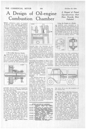
T"well-known name of Leyland Motors, Ltd., Leyland, Lancashire, appears in patent No. 415,880 describing in conjunction with S. Markland, a design of combustion 'chamber for use in compression-ignition engines. The main claims are based on the provision of a cylindrical combustion chamber, connected with the cylinder by a tangential passage. The accompanying drawing shows one of several designs. In this case the chamber (2) is bored in the cylinder head and closed by a plug (1) ccntaining the injection nozzle. The tangential passage (3) is claimed to produce an even rotation of the compressed air in the chamber. It is necessary to inject the fuel in a direction parallel to the walls of the chamber, for by this means an even progressive intermixture is obtained.
A Reversible One-way Clutch.
AA ONE-WAY clutch that can be reversed in its action, by a simple lever movement, is shown in patent No. 414,617, by C. H. Richards, 173, Harvard Avenue, Boston, U.S.A. This device operates on the jamming-roller
principle, that is, rollers are trapped by the drive between a sloping cam-track and the outer casing.
In the drawing, the outer casing (1) forms one element, the other being provided by member 2 connected to the right-hand shaft. The outermost portion of 2 is slotted in an axial direction at several points and rollers (6) are carried in the slots. An inner member (7) is freely mounted on the central Spindle and has sloping notches in its periphery under 'each roller. These notches are not all cut in the same direction; however, half the total being arranged in a sense opposite to the rest. If the central member (7) be left uncontrolled, no drive will take place, owing to the rollers being at rest in the bottom of their notches; upon rotating this member, however, one or other of the sets of rollers will run up its slope and transmit the drive.
The particular set of rollers chosen n46 depends upon the direction of the initial rotation of the central Member. . This is externally controlled by a lever (3) moving a nut-ring (9) screwed internally with a quick-thread. A corresponding thread is cut on an extension of the inner member (5), so that sliding the nut-ring gives the slight turning movement necessary to initiate the drive.
Increasing Accessibility in Rear Axles.
E'ROM Daimler-Benz A.G., of Stutt gart Untertiirkheim, Germany, comes a design of rear-axle assembly for which ease of manufacture and accessibility are claimed, it being possible to remove the whole differential mechanism through t h e cover-plate. The patent is numbered 415,507.
The drawing shows the essential feature of the desig n, comprising a three-piece member, bored to receive the axle bearings, and having a turned flange at the top which is bolted into a recess bored in the axle casing. This recess can be machined at the same setting as the drive-shaft bore, thus simplifying manufacture. The two partial flanges, shown at the bottom of the drawing, locate in a bore at the rear end of the casing, that is, adjacent the cover-plate, so that the whole differential assembly is rigidly held in position, although it can easily be extracted. Using the Engine as a Brake..
ASIMPLE valve intended to be placed between the carburetter and the engine for the purpose of cutting off the mixture and substituting air for braking purposes is described in patent No. 415,365 (void) by P. H. J. Gheerhaert and C. F. Lantier, 143, Nouvelle Cite Jardin et Drancy, France. The
device consists of a tube containing a butterfly valve (3), which can completely close the bore, in conjunction with a disc-valve located upon the top of the body for the admission of air. This valve has ports (2) cut in it which register with similar ports leading to the bore. It is stressed that the disc valve must have a good seating surface, and preferably be ground in.
The lever (4) is for the reception of the control rod.
A Moving Floor with New Features.
A SELF DISCHARGING conveyer ti floor for vehicles is shown in patent No. 415,705 by G. L. Fisher, 561, Old Kent Road, London, S.E.1, and Bright and Galbraith, Ltd., 7, Martin's Lane, London, E.C.4. In this case the floor is built up of a number ot transverse slats, which are hinged to those on each side. A special form of slat and joint is described, the object being to minimize leakage between the joints. Sprockets are mounted fore and aft to transmit the drive, which may be by hand or power, and a self-tripping device to prevent over-running of the limits of movement is described. This is necessary owing to the fact that only the upper portion is constructed as a floor, the underside consisting of chains alone.