


For DRIVERS, MECHANICS & FOREMEN.
Page 59
If you've noticed an error in this article please click here to report it so we can fix it.
TEN SHILLINGS is paid to the sender of any letter which we publish on this page, and an EXTRA FIVE SHILLINGS to the sender of the one which we select as being the best each week. AN notes are edited before being published. Mention your employer's name, in confidence, as evidence of good faith. Address, D., M. and F., "The Commercial Motor," 7-15, Rosebery Avenue, London, E,C. 1.
Lamps Alight, On Saturday, October 16th, light your lamps at 6,34 in London, 6.39 in Edinburgh, 6.33 in Newcastle, 6.44 in Liverpool, 6.40 in Birmingham, 6.44 in Bristol, and 7.21 in Dublin.
A Rig for Testing Sparking Plugs.
The sender of the following communingtion has been awarded the extra payment of Sc. this week.
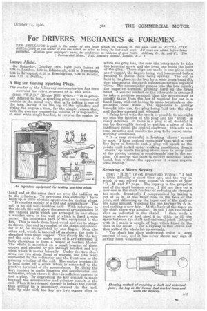
(2146) "W.,I.D." (Herne Hill) wiites: " It is generally difficult to test a, sparking plug on a commercial vehicle in the usual way, that is by taking it out of the hole, laying it on the top of the 'cylinders and giving the engine a, turn, for the simple reason that, with the average commercial vehicle, it is impossible, single-handed, least when sgle-handed, to revolve the engine by ,hand and at the same time see over the radiator on to the, cylinders.To overcome this difficulty I have built' up a, little electric apparatus for testing plugs. "It consists mainly of a coil and accumulator. The coil is an old non-trembler unit. With reference to the sketch this will show the general arrangements of the various parts which are arranged in and about a, wooden case, in the wall of which is fixed a voltmeter. An important part of the equipment is the key. This is made from hard wood and cut to shape as shown. One end is rounded to the shape convenient for it to be manipulated by one finger. Near the other end, which is tapered off as shown, the body is sheathed with sheet copper. This closely fits the key and the ends of the under part of it are extended in both directions to form a couple of contact blades. The whole is mounted on a small bracket of sheet copper and pivoted by pin through bracket and key, upon which it moves laterally. "Under the two short arms are two studs (head of screws), one (the rear) connected to the voltmeter and the front one to the primary winding of the coil. The centre bracket (B) is held down by a screw which is connected to the positive terminal of the accumulator. By lifting the key, contact is made between the accumulator and voltmeter, which shows if there is sufficient current to test a plug. By depressing the key contact is made between the accumulator and primary circuit of the coil. When it is released sharply it breaks the circuit, thus setting up a secondary current in the coil. Side by side with the key are two copper clips in which the plug lies, the rear one being made to take the terminal screw and the ft-tint one holds the body of the plug. These clips aro made in one piece from sheet-copper, the fingers being well hammered before bending to insure them being springy. The 'coil is held in its place,in,the box by a, wide brass band (E), that also actstas the.earth connection for the negative wires: The accumulator pushes into the box tightly, the negative ,terminal pressing hard on the brass band. A similar contact onthe other side is arranged to take a positive terminal, thus the accumulator is quickly taken from the box if required for use in a hand lamp, without having to undo terminals or disentangle loose wires. the apparatus is quickly brought into use the plug being laid into the clips and the key pressed and released. "Being level with the eye it is possible to see right up into the interior of the plug and the short is easily detected, if there is a plug at all doubtful it can be thoroughly tested by putting a piece of thin cardboard round the central electrode ; this acts as. a semi-insulator and enables the plug to be tested under Working conditions. "It is very successful in locating 'shorts' caused by soot. • I have noticed repeatedly that with a, very fine la,yer of benzoic> soot a plug will spark at the points until tested under working conditions, thentit shorts' up inside the plug about once to every four at the points, causinr,cr a considerable loss in the engine. Of course, the fault is quickly remedied when found, but without the apparatus it would require some finding."
Repairing a Worn Keyway.
(2147) " (West Bromwich) writes: "I had a little difficulty a short time ago, and the way in i.vhich it was solved may appeal to readers of your 'D., M. and F.' page. The keyway in the propeller end of the shaft became worn. I did not dare .cut‘a, new one in the shaft for fear of reducing its strength too much. Eventually I compromised by taking a cut of in. of the taper hole in. the boss of the joint, and skimming up the taper end of the shaft to the same amount, widening the one keyway by -Am in. and making a new key. At the back of the taper on the shaft there was a collar. In this I cut two' broad skits as indicated in the sketch. I then made a tapered sleeve of tool steel -13in. thick, to fill the space between the shaft and universal joint. Integral with it I made a couple of tugs which fitted in the slots in the collar. I cut a. keyway in this sleeve and then nutted the whole lot up securely. " The shaft has since undergone quite a large amount of use, and it has never shown any sign of having been weakened."