


Patents Completed.
Page 24
If you've noticed an error in this article please click here to report it so we can fix it.
Complete specifications of the following patents will be sent to any address in the United Kingdom upon receipt of eightpence per copy at the Sale Branch, Patent Office, Holborn, W.C.
ELECTRO-MAGNETIC CLUTCH.— Hill.—No. 16.095, dated 10th July, 1909. —This clutch is of the type which operates by magnetic pull only, and not by the friction of surfaces drawn together by an electro-magnet. The driven portion of the clutch is recessed on one face and carries a number of outer and inner laminated iron rings, forming an annular space between them. The inner periphery of the outer rings and the miter periphery of the inner rings are provided with teeth which form pulepieces. The driven member of the clutch, which is keyed to the driving shaft, carries a number of laminated annular discs, which are disposed in the annular space between the discs carried by the driving member. The discs carried by the driven member are formed with teeth on their outer and inner peripheries and coils of wire are wound on these teeth and short circuited upon themselves. The laminated discs on the driving member of the clutch are excited by coils arranged in the recess portion of the driving member, and these coil= are connected to rings to which current is supplied by means of brushes. The operation is as follows :—Current is switched on to the exciting coil of the driving member and a magnetic flux is thereby set up in the metal surrounding these coils, which flows through the laminated discs on the driven member of the clutch. Current is therefore induced in the short-circuited windings, and the force exerted by this current causes the driven member to rotate. As the driven member increases in speed. the induced current will decrease, while the pull of the pole-pieces in the direc
tion of rotation increases. When the driven member attains the same speed of rotation as the driving member, power is transmitted solely by the magnetic pull of the pole-pieces.
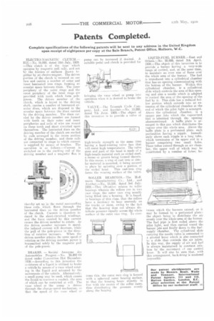
BRAKES. — Societe Anon-eine des Automobiles Peugeot.—No. v25.892;09 dated under Cenvention 31st December. 1908.—According to this invention the resistance of a liquid is utilized to brake a vehicle by means of a vane wheel rotating in the liquid and actuated by the movements of the vehicle. AlternaCively, a small pump may he used, which causes the liquid to traverse A conduit, the area of which can be restricted at will. The vane wheel or the pump is driven through the change-speed mechanism, en that the speed of the vane wheel or pump can be increased if desired. A suitable pedal and clutch is provided for
bringing the vane wheel or pump into operation when it is desired to brake the vehicle.
VALVE.—The Triumph Cycle Company, Ltd.. and Another.—No. 13,285. dated 7th June. 1909.—The object of this invention is to provide a valve of high-tensile strength at the same time having a hard-wearing valve face that will resist high temperatures. The valve stem and part of the head is made of a high-tensile material such as nickel steel. a recess or groove being formed therein. In this recess, a ring of cast iron or similar material is mounted, it being secured in place by spinning over a portion of the nickel head. This cast-iron ring forms the wearing surface of the valve.
ROLLER BEARINGS.—The Hoffmann Manufacturing Co., Ltd.. and Another.—No, 15.556. dated 3rd July. 1909.—This ins:cation relates to roller bearings wherein the rollers run in two race rings, the outer race ring usually icing fitted into a housing. It is found. in bearings of this class, that the rollers have a tendency to bear unevenly on the tracks or races, owing to the fact that the housing does not always distribute pressure equally across the whole surface of the outer race ring. To over come this, the outer race ring is formed with a spherical outer bearing surface, so that the housing bears directly in line with the centre of the roller races, thus distributing the pressure evenly along the bearing LIQUID-PURL RURNER.—East and Others.—No. 20,958, dated 5th April, 1909.—The object of this invention is to provide a burner having a very-wide range of control, and, at the same time, to maintain an even size of flame over the whole area of the burner. The fuel is introduced into a cylindrical chamber that has an opening communicating with the bottom of the burner. Within this cylindrical chamber, is a cylindrical slide which controls the area of this opening and aloe a needle which is adapted to control the area of the opening of the fuel by it. This slide has a reduced hollow portion which extends into an extension of the cylindrical chamber at the end of which the pilot light is arranged. Above the cylindrical chamber, is a square pan into which the vapourized fuel is admitted through the opening aforementioned. A baffle plate is arranged in this pan which distributes the vapour over the whole area. Above the baffle plate is a perforated plate. each perforation having a nipple. Immediately above each nipple is a long tube, which terminates at its upper end in a burner comprising two small holes. These tubes extend through an air chamber, the upper wall of which may be constituted by a number of tubes. be tween which the burners extend. or it may be formed by a perforated plate: the object being to distribute the air evenly over the whole area of the burner. The fuel pipe is first coiled above the pilot light, and then carried round the burner jets and finally down to the fuelsupply chamber. The cylindrical slide carrying the needle valve is connected to a pivoted lever which is also connected to a slide that controls the air inlets. In this way, the supply of air arid fuel is always maintained in constant relation by the movement of one control lever. It will also he seen that, with this arrangement, back-firing is rendered impossible